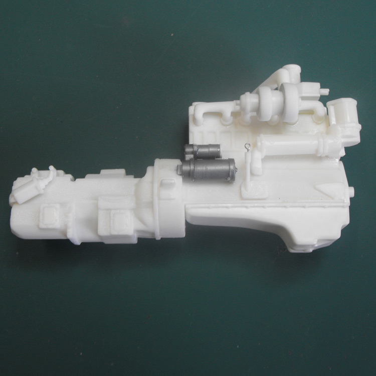
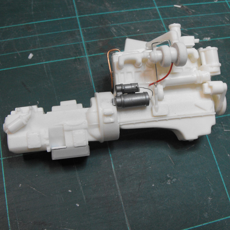
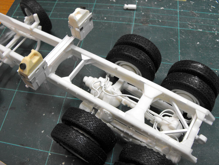
I replaced the starter motor with bits from the spares box and added a bit of plumbing. This is the first truck I have made in 25 years, so I have a fairly steep learning curve as far as plumbing and detailing goes. I added a bit of wiring and piping with fuse and electrical wire. It is largely representative as, again, I'm a bit short of reference despite hours of websearching.
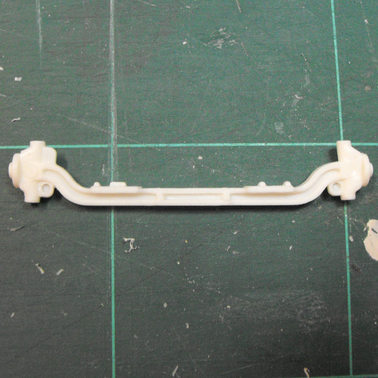
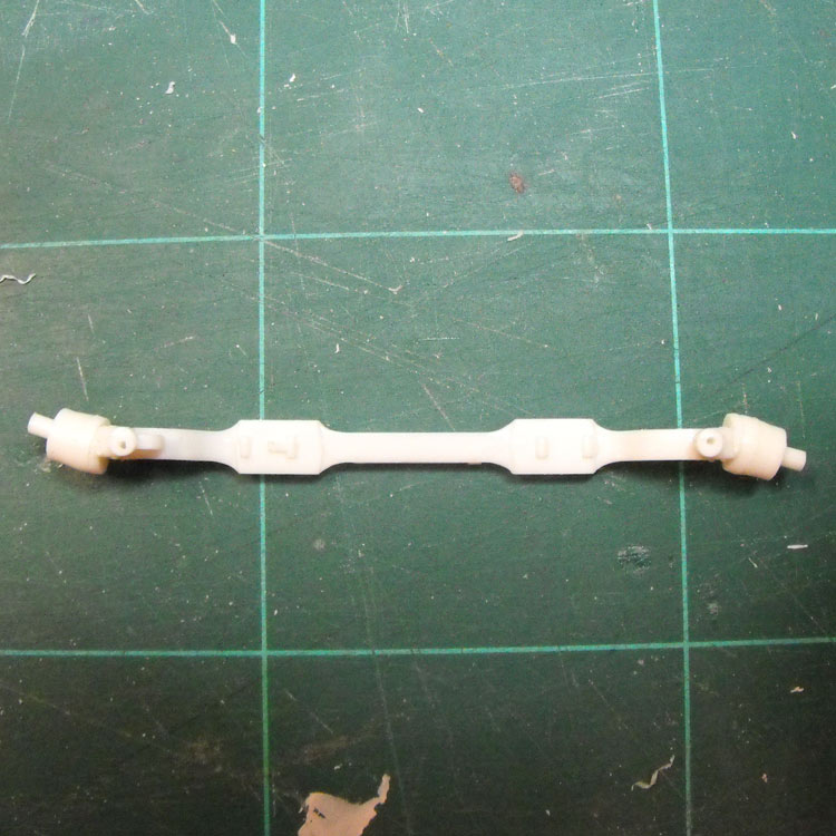
I wanted to have the front wheels steerable, or at least posed at an angle. The kit parts made this quite hard and I nearly destroyed the front beam in my attempt. I went with option two and simply sanded the ends down on my disc sander at 15°. This provides a simple and robust solution with minimal loss of hair.
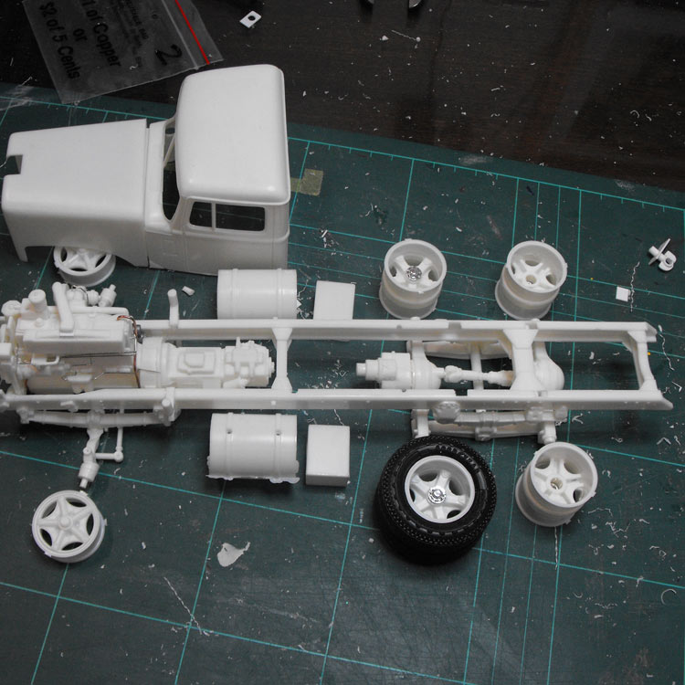
I started glueing ancillaries, diffs, tanks, batteries, suspension and frame together. It was at this stage I realised I should have shortened the chassis! The kit has a sleeper while my subject doesn't. Okay. Back to the references to have a think about the best way to handle this. Fortunately I discovered the problem in a dry run before I had got much further than glueing the frame together. Watch this space for the fix.
I discovered a second error while creating the schematic. The kit tanks are 10 mm short. I scabbed a pair out of a "Madame Butterfly" Mack kit. I'll cut these down to size and sand off the lumps, bumps and chrome.
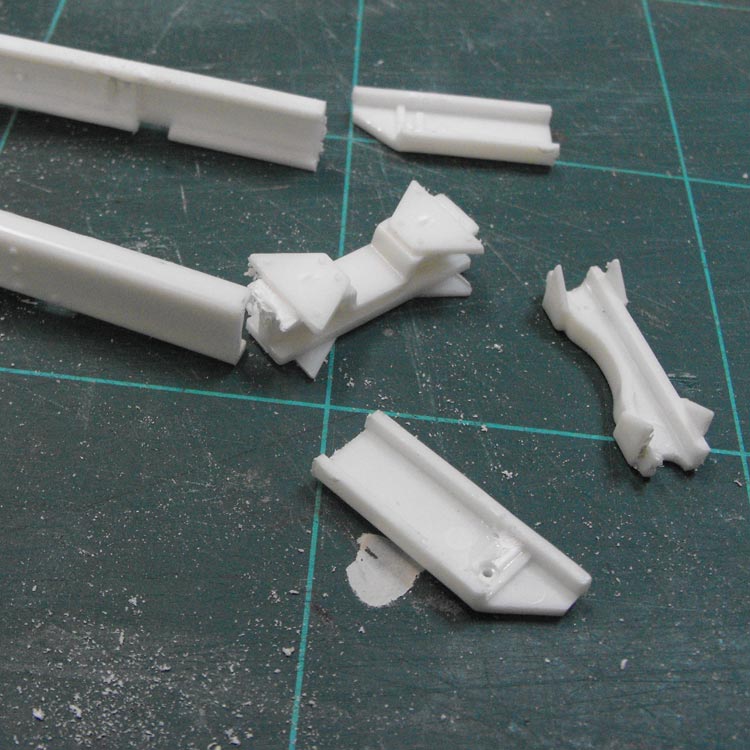
Here is the chassis solution. Fortunately the glue had not completely cured so I was able to pry the parts apart with doing too much damage. I then cut 30 mm off the tail end of the chassis and re-chamfered the rails.
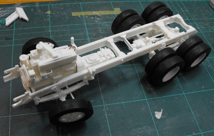
I cleaned up the parts and then re-assembled them, with a new cross member toward the front as well. With the chassis frame sorted out I could mount the rear suspension and get the wheels on to make sure everything sat nice and level.
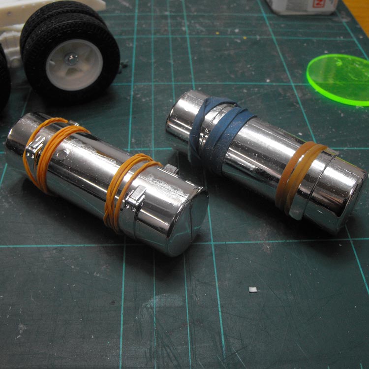
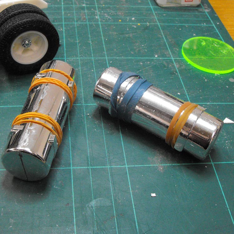
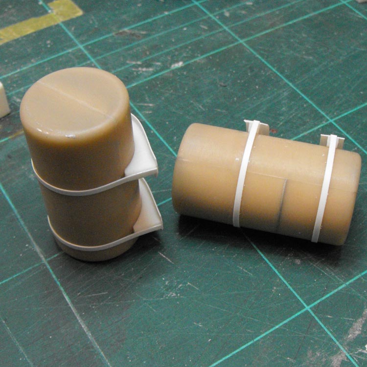
On to the tanks. The donated tanks were glued up and left to set.
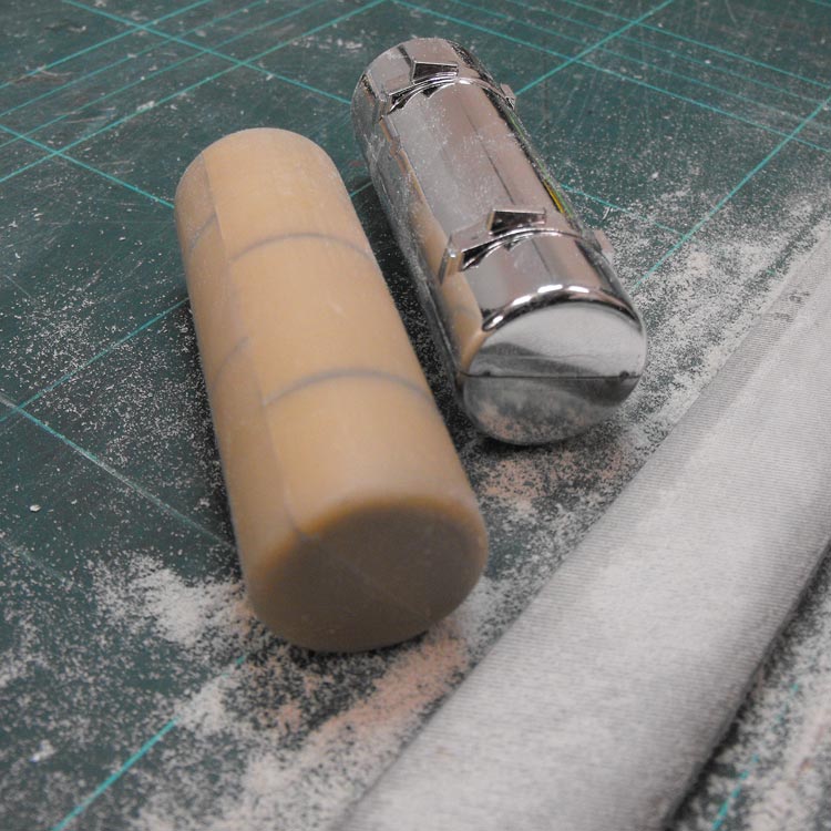
Once the tanks were cured I removed all the moulded-on strap and bracket detail(?) with a big flat bastard.
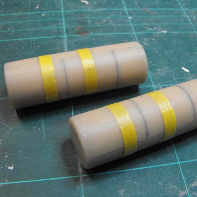
Next comes the surgery. I marked off the two cuts on each tank with Tamiya tape as a cutting guide.
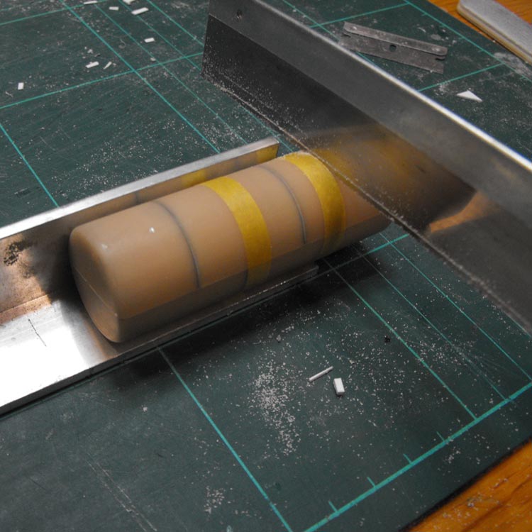
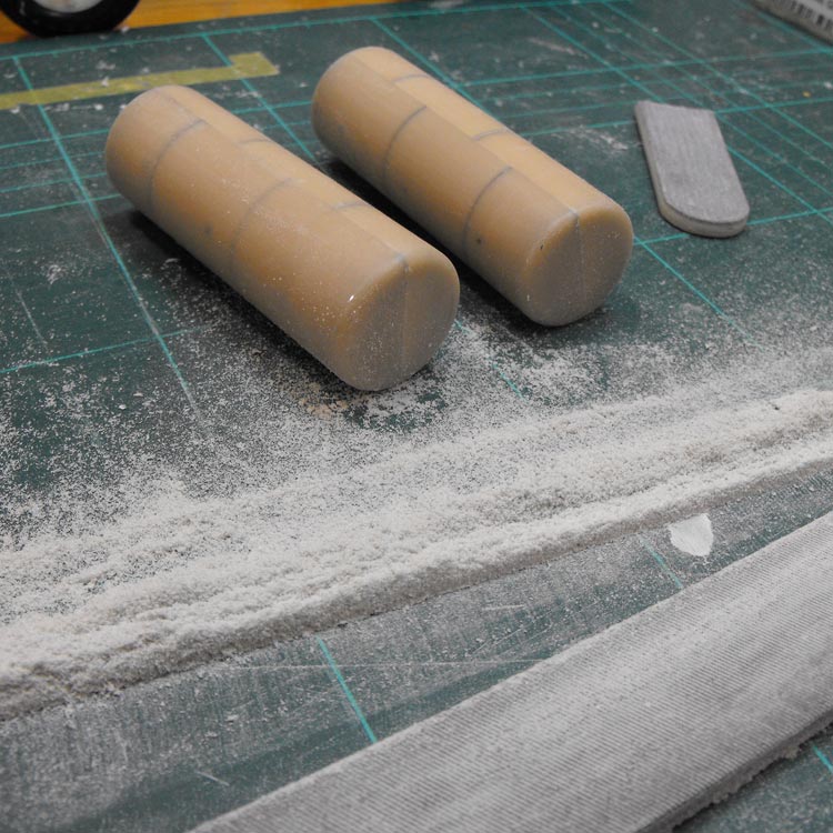
Cutting round bits is always such fun! I worked out a new cutting aid this time. I found a discarded piece of aluminium L-section and simply held the tank against it with my hand. This provided ample stability for the cut and the tank didn't squirm around at all. Sort of an improvised mitre box. Anyway - it worked a treat.
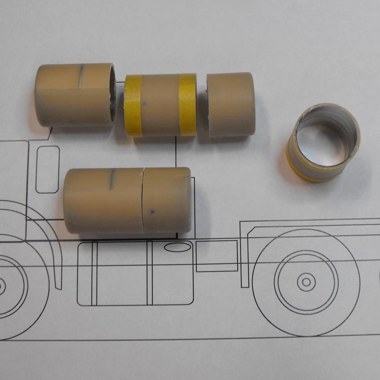
Here's the reason for the different cut lengths. With a bit of careful planning, (and doing the drawing FIRST this time!) I managed to position the join where it will be covered by the new straps. Up here for thinking!
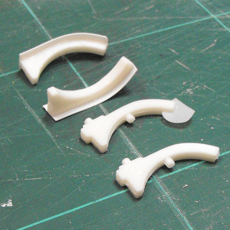
I thought the kit tank brackets coud be improved quite easily with a clean up and a thin strip of styrene.
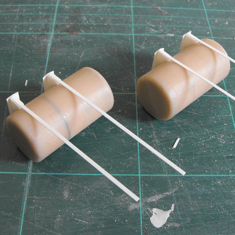
With the brackets glued in place on the tanks, I wrapped some more styrene strip aronud the tanks to replace the moulded-on straps they originally had.
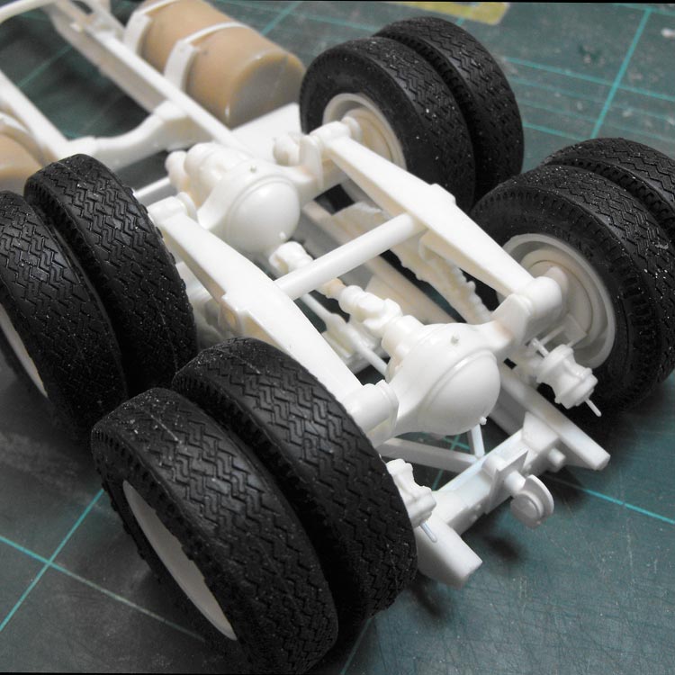
I also added some detail to the rear suspension. I raided both International Transtar kits in my stash to get enough air brake bits for front and rear spots on the bogie. I don't know what I'll now use on the Transtars, but I'll cross that bridge when I come to it. I also scratched up trailer hitch and associated mounting hardware. Here's another dry run.
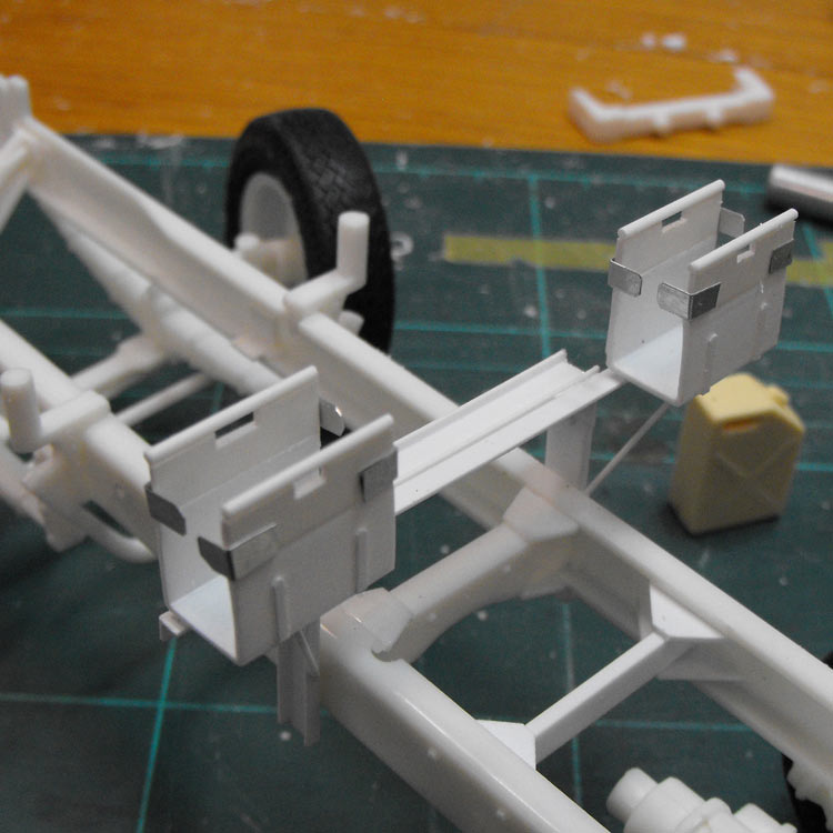
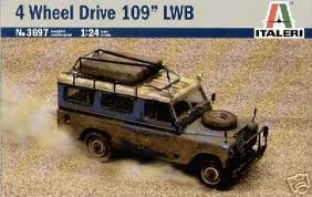
The original unit has a frame added at the rear of the cab mount to hold some jerry cans and and the suzies. Here's the frame and jerrycan racks scratched up.
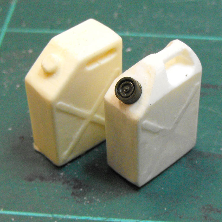
The Auslowe water cans left something to be desired, so I applied drill, file and knife to get a more appropriate shape, and replaced the moulded-on filler cap with the end cap from a 1:48 TOW missile tube, I think!
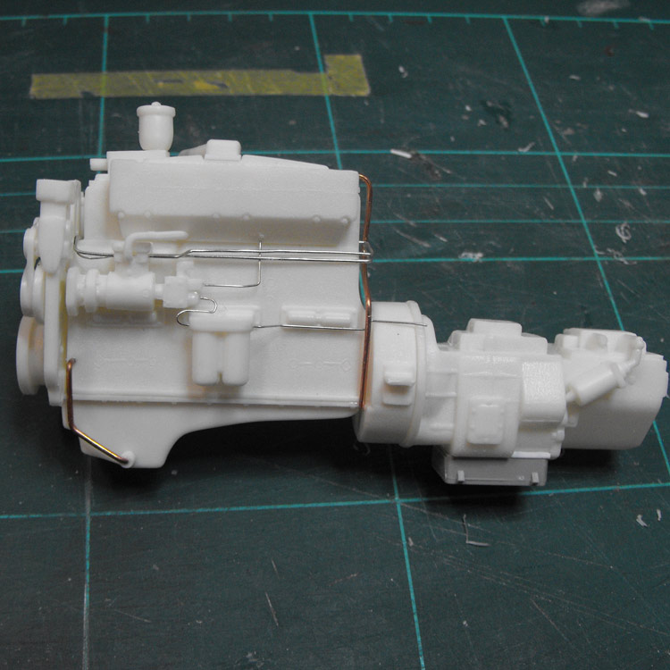
Next op was some plumbing for the back brakes. Here are the air hoses. Pipes and wiring harness yet to come.
I picked up a couple of Italeri 1:24 Land Rovers. I figure at one of these will make a good load with some general cargo.

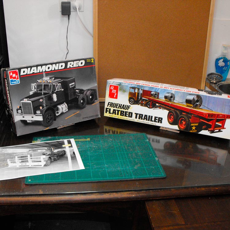
I cracked open the trailer kit and pulled out the one-piece tray and the Land Rover body and popped it on the back to see how it will all look together. It's been so long since I've done a big rig that I am really surprised how big the model is going to be.

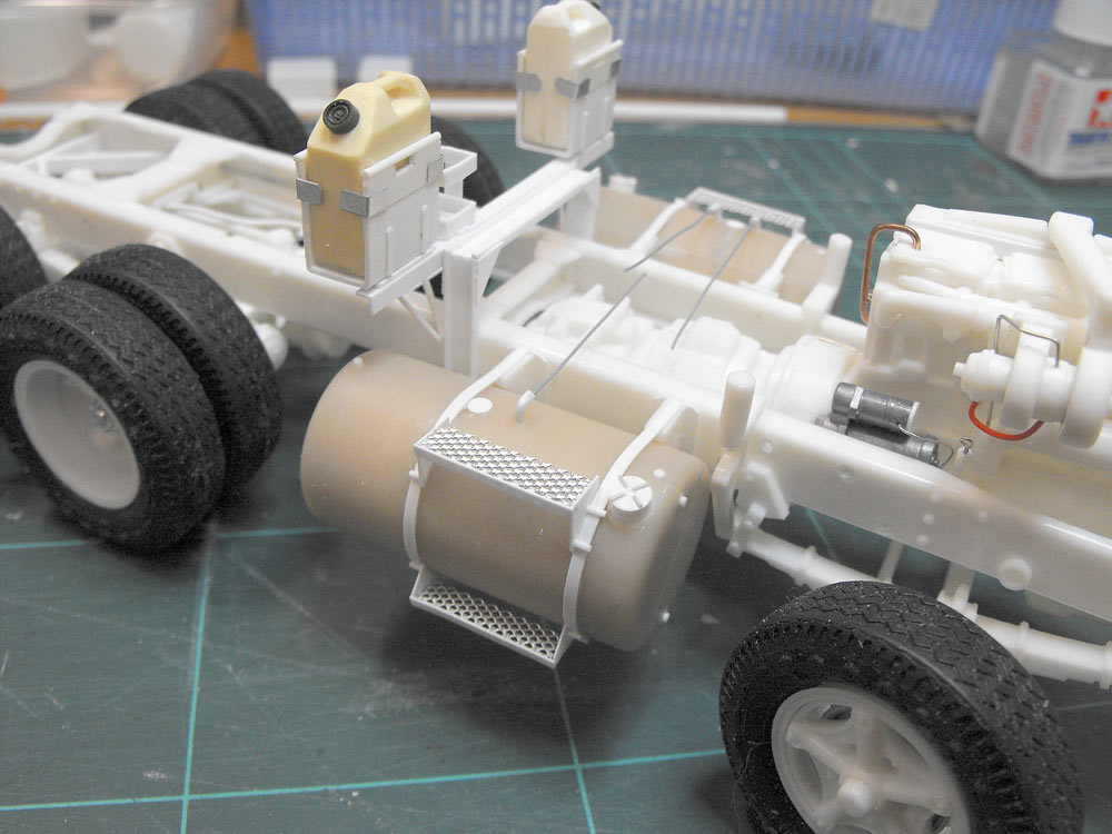
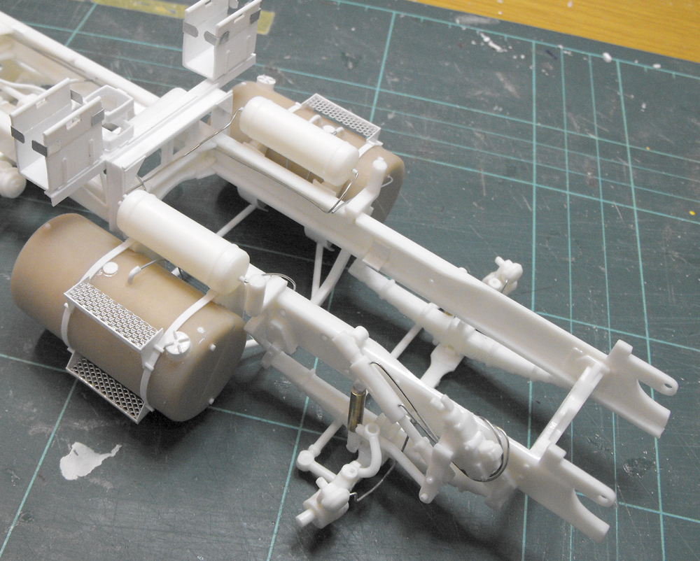
Quite a bit more detail was added to the tanks, including metal mesh steps and plumbing. They were fitted and the fifth wheel dropped in place temporarily. I am starting to get a feel of how chunky this truck is. A short wheelbase and dual drive will do that.
Here it is with the cab off so you can see a bit more detail.
With the Aussie truck being RHD, the steering box and linkages needed to be transferred to the other side of the chassis. This involved cutting the uni-joint off one end of the box and glueing it on the other end. The box was then glued updside-down on the other chassis rail. There was also a gaping hole in the back of the box that I blanked off with some card. All the attachment lugs on the LH chassis rail were pared off as they weren't needed any more. They were also set up for a forward set axle, so they were in the wrong spot for this truck.
The linkages themselves needed some re-arranging and shortening to look feasible on the RHD set up.
Three air tanks were added and then these, the front brakes and the power steering had some plumbing added.
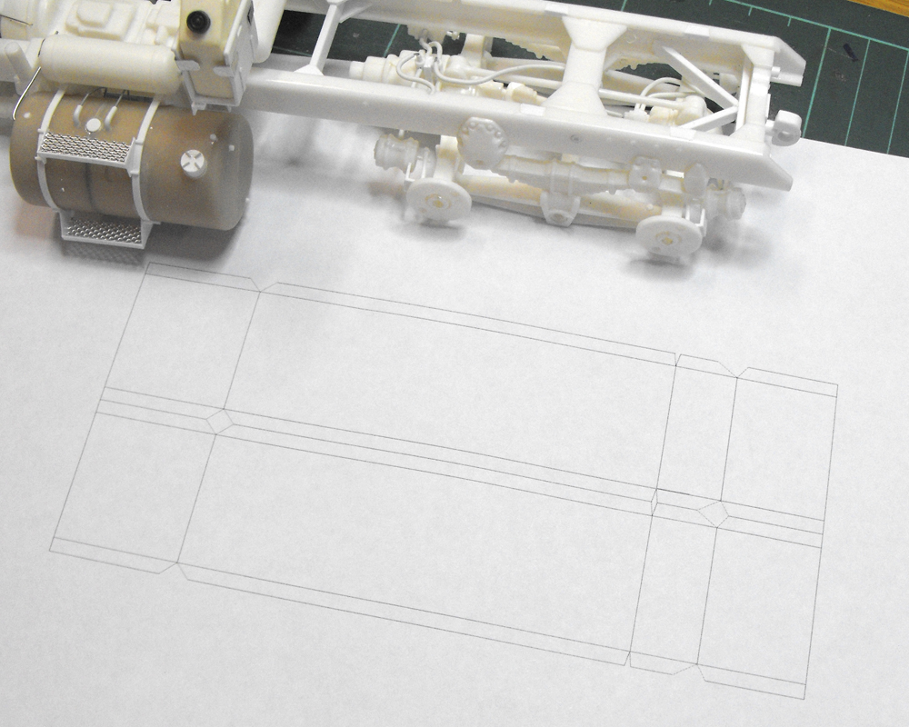
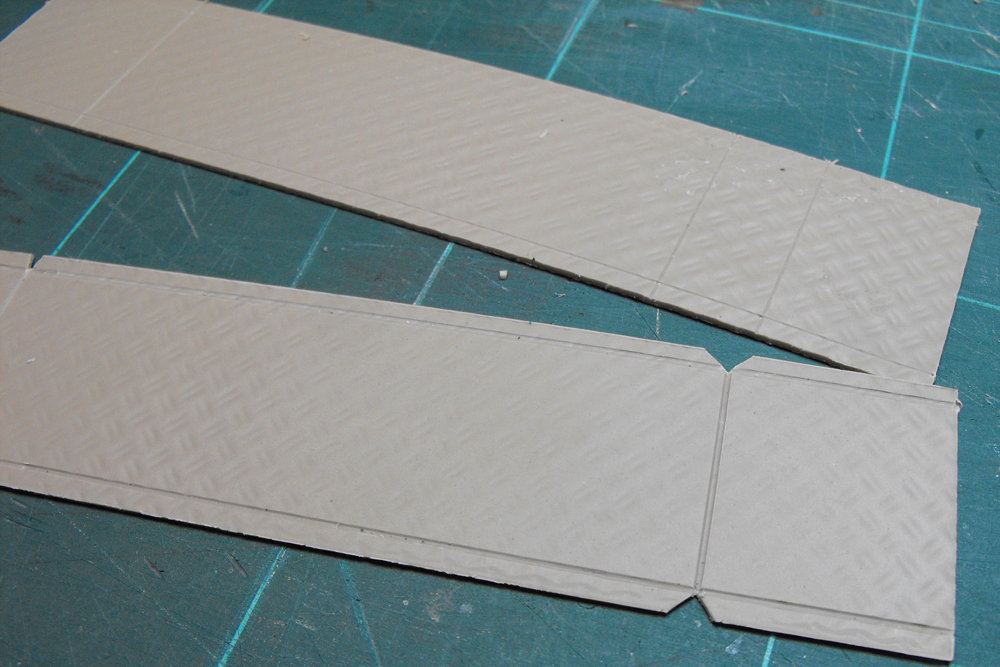
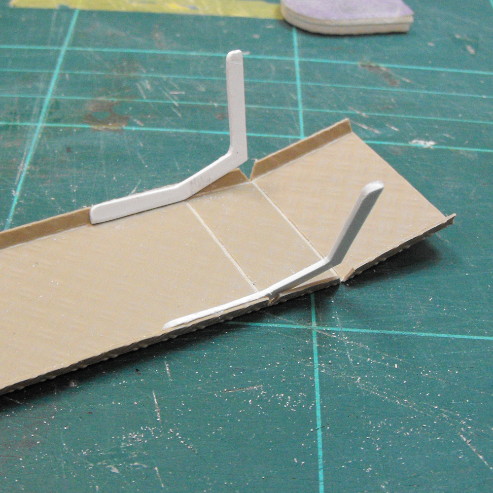
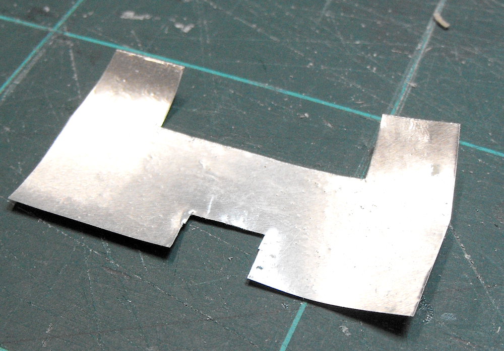
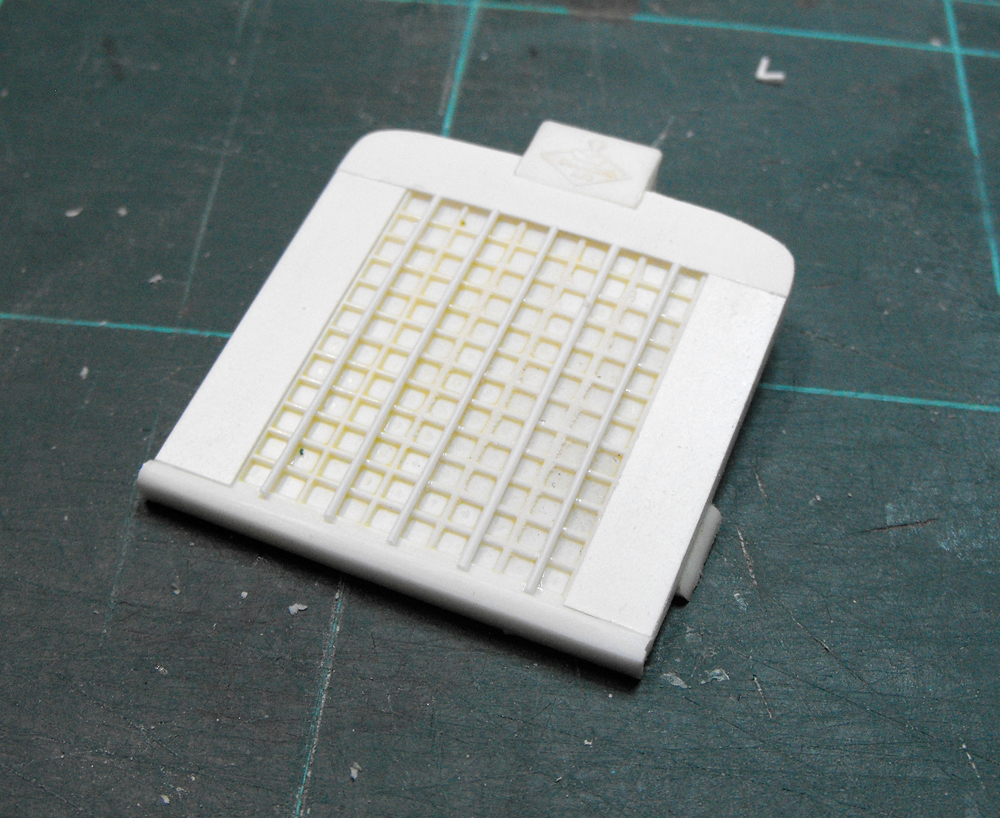
The museum example I got most of my pics from had plastic rear guards fitted but shots of the trucks in Vietnam show a square fabricated treadplate rear mudguard arrangement. I drew up a template in Illustrator and ran out a print as a test.
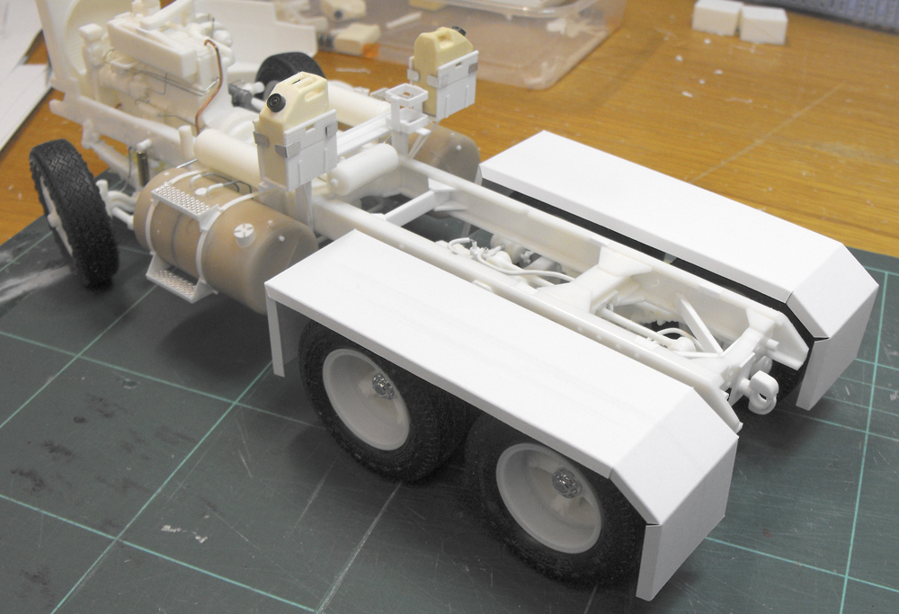
When trimmed and folded they fitted quite well. Now I just have to do the same thing with some styrene treadplate!
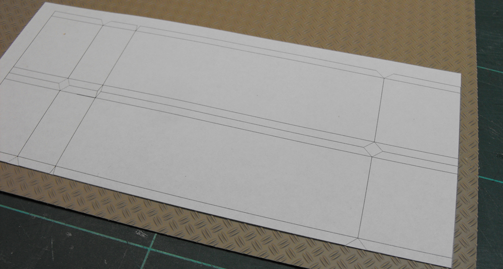
I printed out another copy of the mudguard plan to use as a template for cutting and forming the plastic sheet.
Having done that, I used a dental tool as a scribe and creased the fold lines.
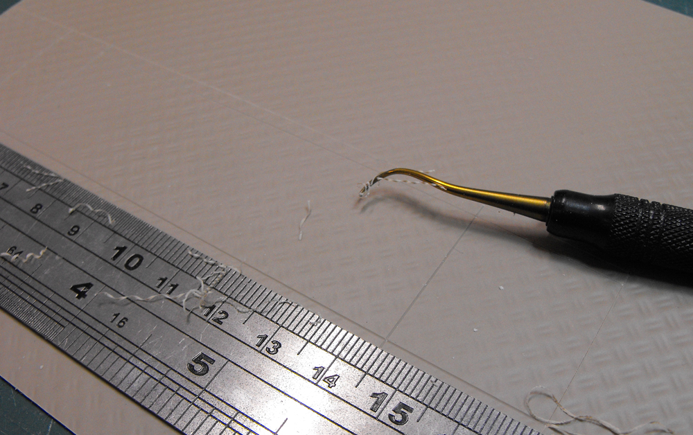
The guards were then trimmed out.
I had one of those surprising coincidences that comes along from time to time. After posting my previous progress on a couple of forums and in my own newsletter, one of my fellow aviation historical society members contacted me. It turned out he actually designed these very mudguards in the 1970s for the local distributor of Diamond Reo trucks and the Australian Army. How's that for it being a small world!
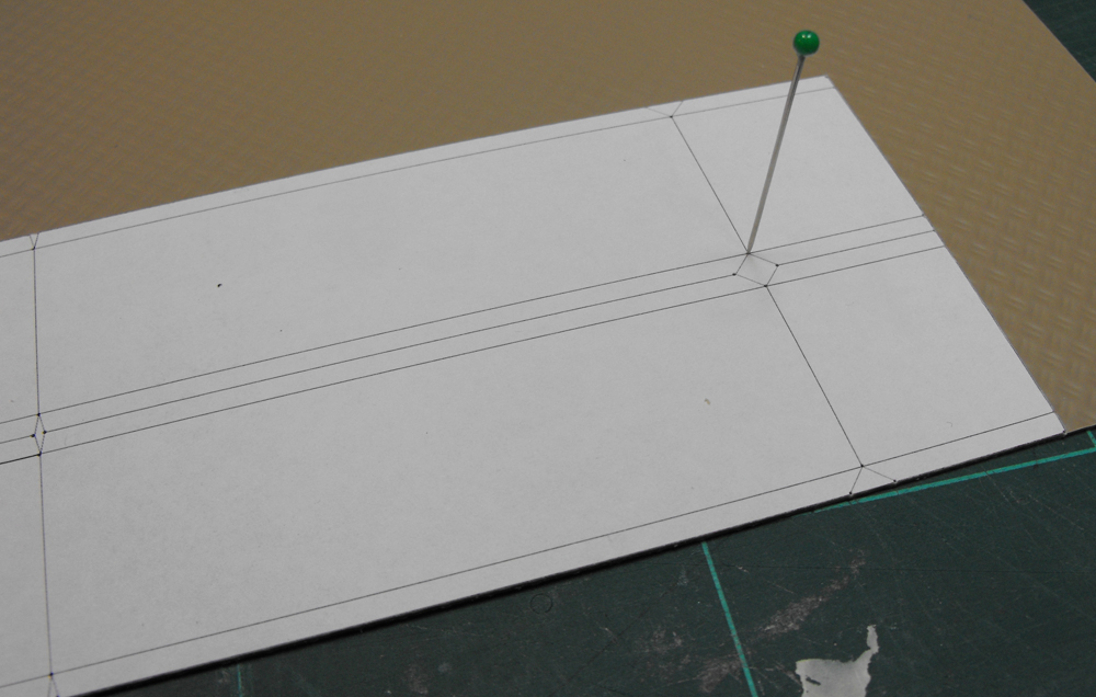
I gave the printed paper a light spray of spray adhesive and tacked it onto the back of the styrene treadplate. Using a glass-head pin, I transferred all corners and fold intersections onto the styrene as pinpricks.
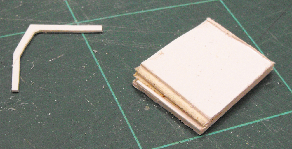
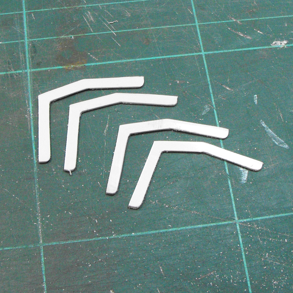
The styrene treadplate has quite a bit of spring in it. In order for it to keep its shape on the bends, I knew it would need some bracing of some sort. I cut out one master to test the fit. This looked like it was going to work, so I stuck 4 squares of styrene together with double sided tape so I could shape them all at once.
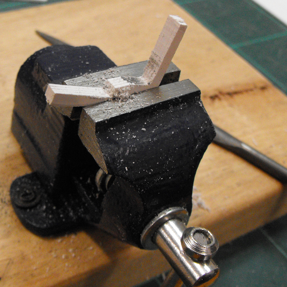
I then sawed and filed the sandwiched sheets to the final shape.
Here they are still stuck together.
The braces were then separated with a scalpel and the tape and residue cleaned off with Dissolve-It cleaner.
The braces were then glued to the folded styrene treadplate.
The rest of the guard end was then glued to the brace, giving the guard the correct shape.
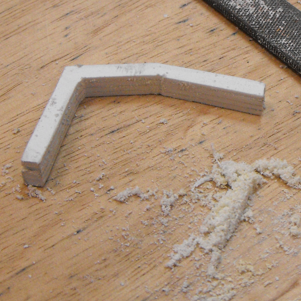
Two problems arse at this stage. The first was that the edges of the styrene were cracking where they folded. I tried many different ways of folding, depths of crease, heating etc. None of these produced a satisfactory result. The second problem was that I ended up with a guard that was 10mm too long. Back to the drawing board!
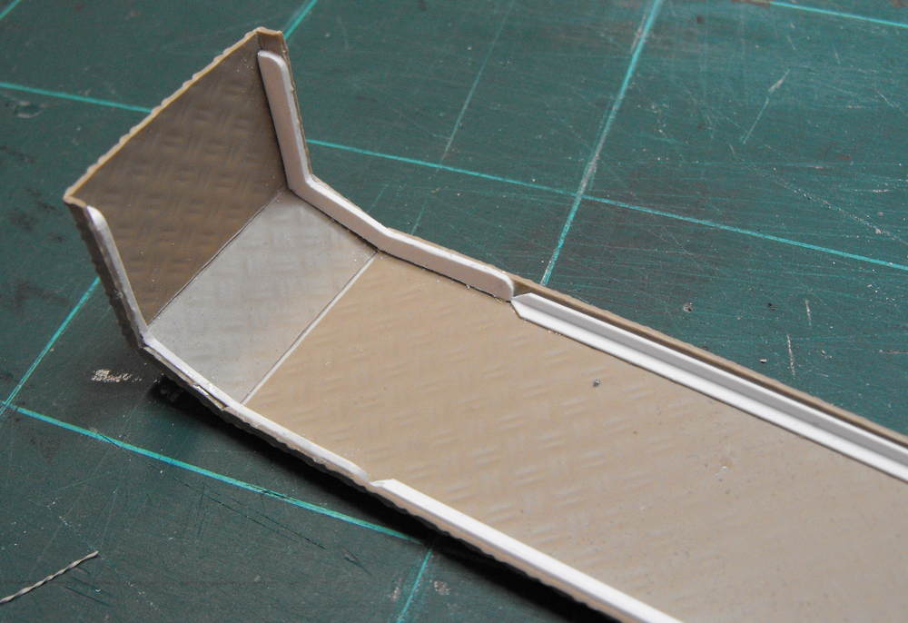
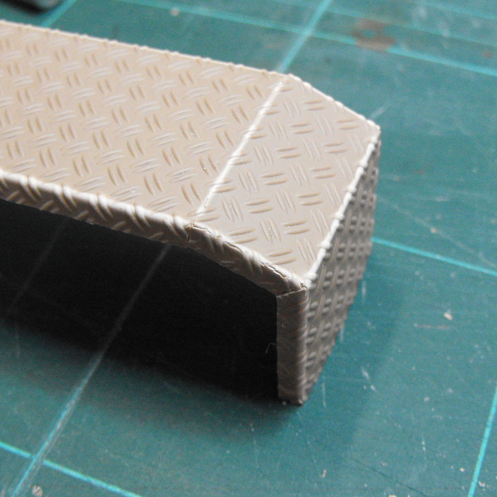
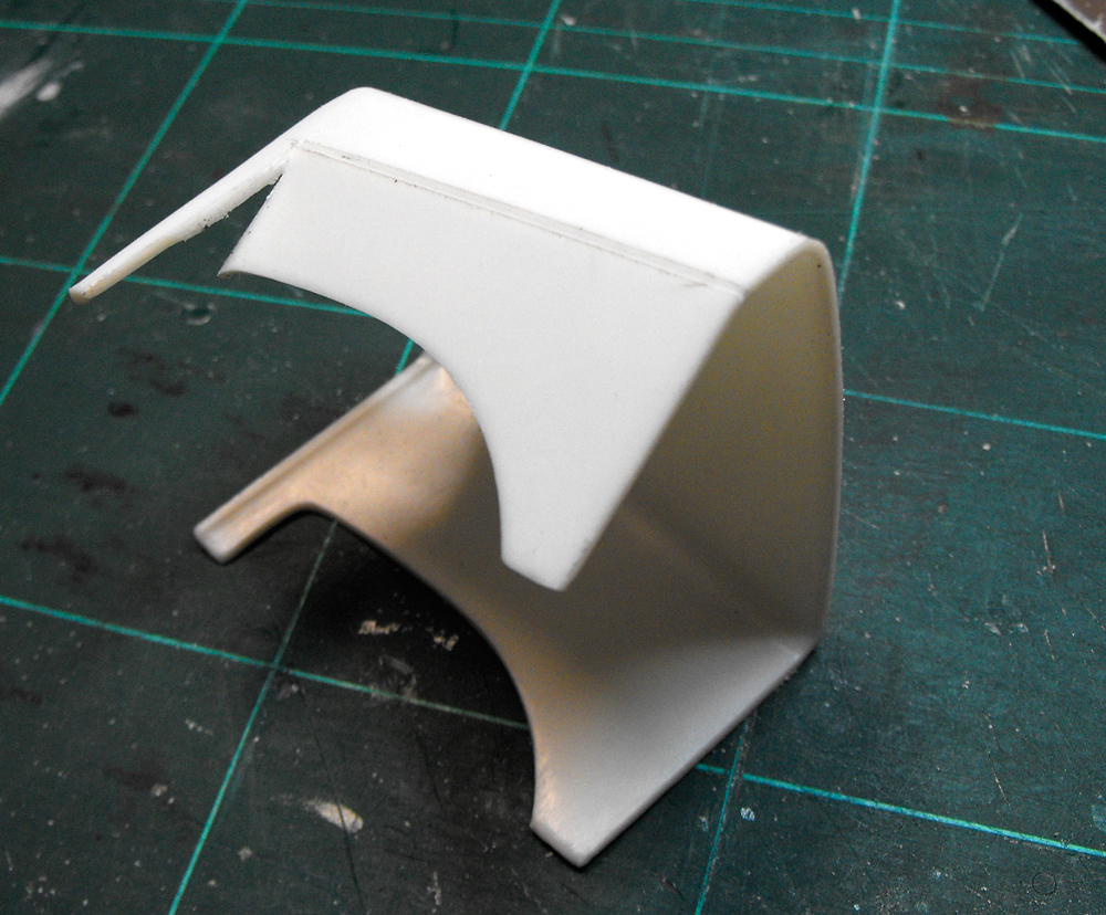
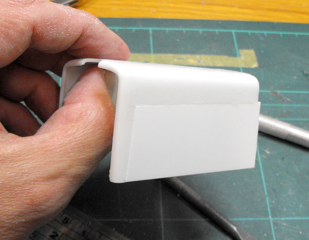
Second attempt at the guards. I have decided to sacrifice the nice folded edge of treadplate and just fabricate them. The right angles were maintained with angled styrene strip. This makes lining things up much easier and adds quite a bit of strength.
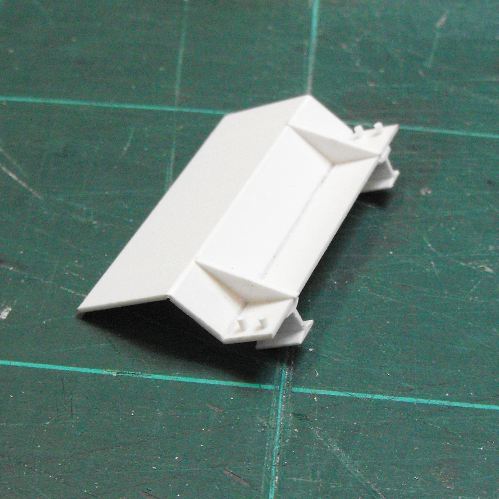
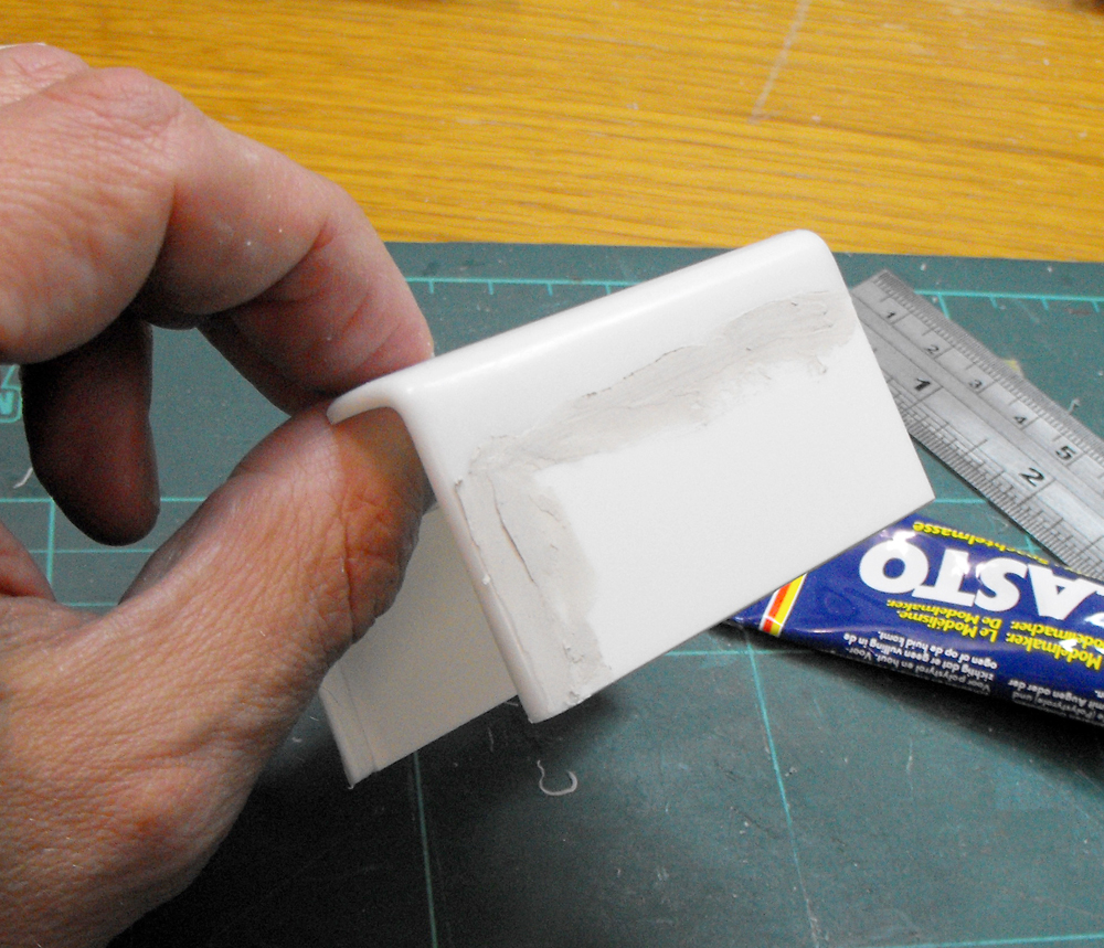
Another unusual feature of the Australian Army trucks was the addition of a sump-guard. This may have been partly due to the sump now sitting in front of the set-back front axle. I fabricated this out of some sheet styrene.
I'm making a start on the interior now. The kit seats had that horrible open-back look to them. Seeing as these rigs had day-cabs, the backs of the seats would be readily visible through the cab glass. I've glued some styrene sheet to the backs of the seats to give them a bit more dimension and realism.
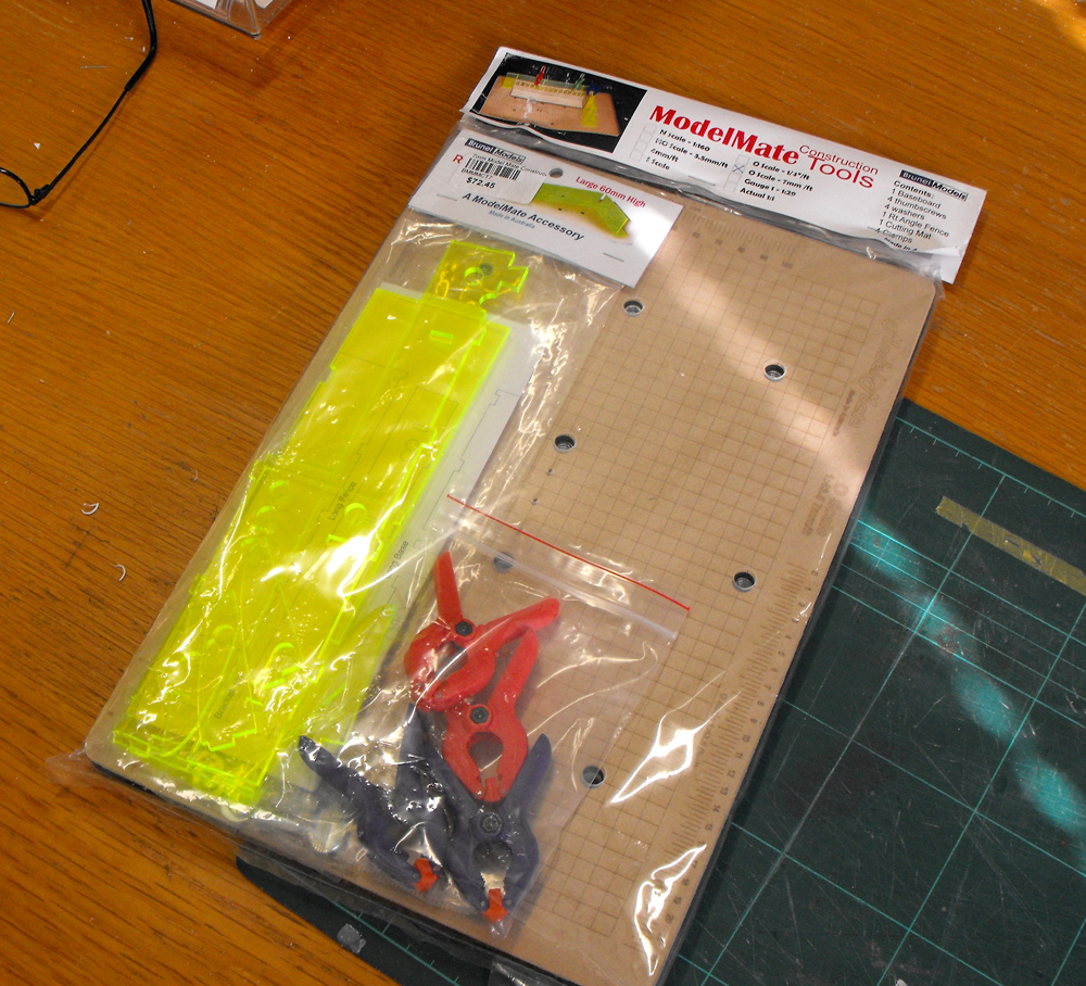
I have found lately that I am fabricating more bits and pieces on my models. Up until now I have always used a basic set square to get parts at right angles. After two unsuccessful attempts with the set square to get a guard set up, I bit the bullet and spent some dollars on a modelling aid. My LHS is Brunel Hobbies. Brunel Hobbies is well known in Australian model railroad world as a key supplier of accessories and tools. They market a gadget, the ModelMate, that helps you get sides square. I believe was designed initially for the railroad crowd to make creating buildings and rolling stock easier. They're not cheap, the version I got was over $70AUD, but they do work.
It consists of a flat base with strategically placed nutserts and a printed grid. There is also a glue-proof cover sheet with a scale grad on it. A set of parts to make up the 90° walls complete the set. The walls are made of very accurate laser cut acrylic and, once glued up with superglue, form a nice and rigid surface to clamp parts to.
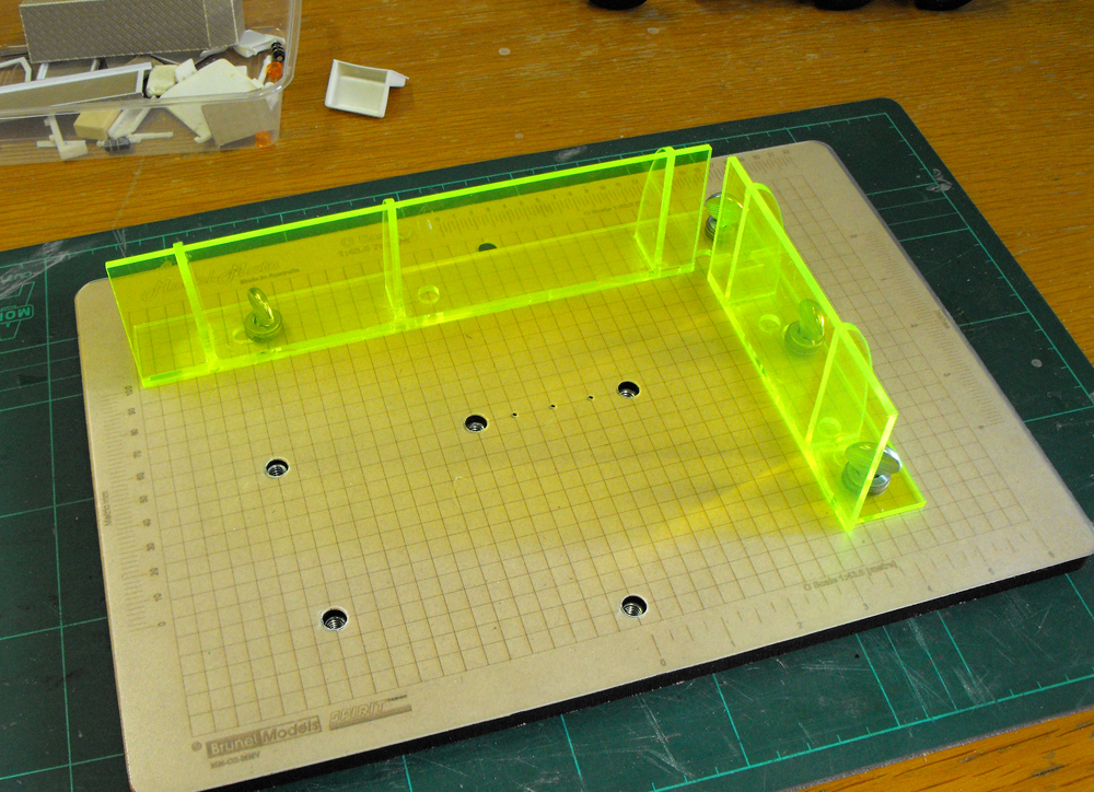
Here is my ModelMate assembled.
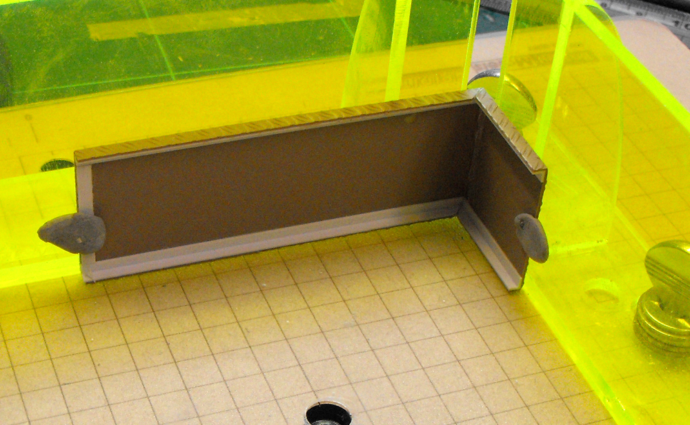
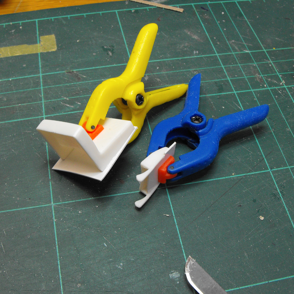
I did find the walls were a too tall for me to use the clamps supplied. Shorter wall sets are available and I'll get one of those next time I'm there. Here is the first guard being held against the ModelMate with blutak for glueing. The mating edges of the guard have been chamfered with a glass nailfile.

It is quite easy to clamp a drawing under the walls to act as a reference. Here I'm using the drawing to get the right angle on the rear drop-off of the guard.
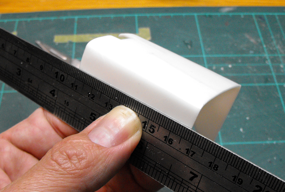
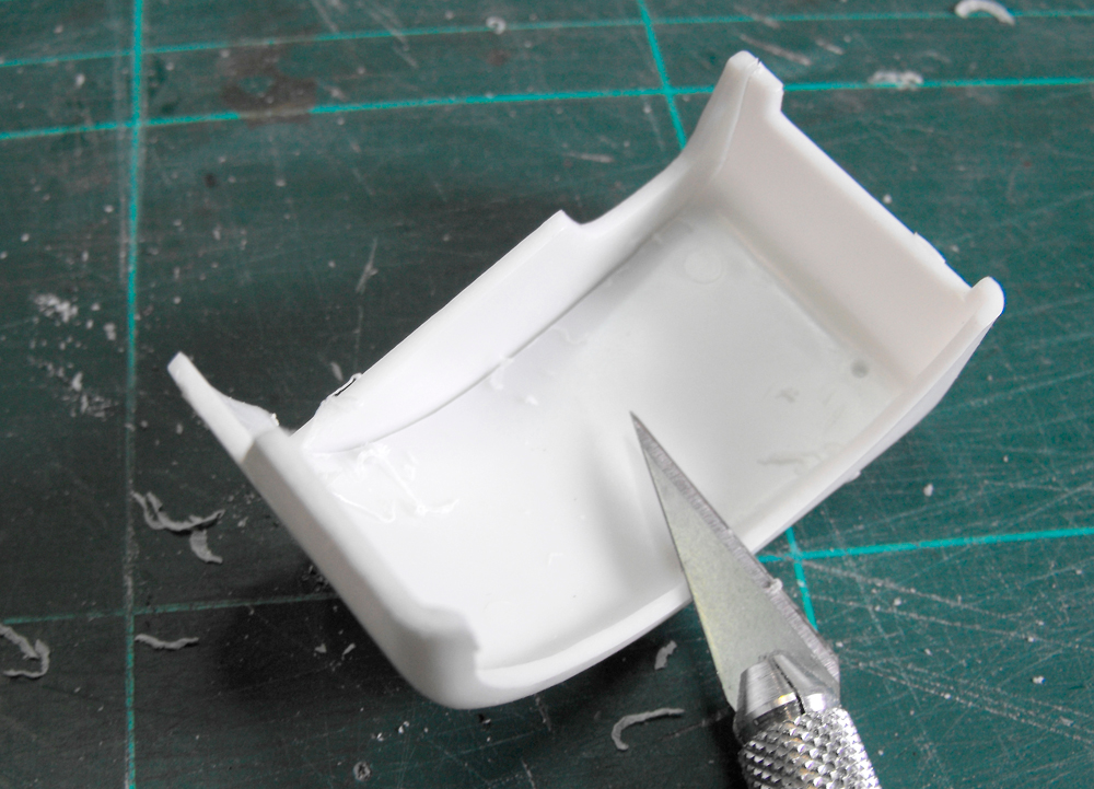
On to the bonnet. Rather than try to fill the existing wheel-arch hole with an odd-shaped plug, I decided to cut a rectangular section out of the side of the bonnet so I could just slot in a piece of rectangular card. I used a steel rule and the back of a hobby knife to score and snap the piece to be removed.
...just like that.
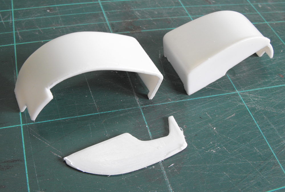
It was simply a matter of replacing the cutout with a plug of sheet styrene.
The bonnet was then filled and sanded.
A piece of metal foil was cut to represent rubber matting on the floor and cover up the holes for the LHD pedals.
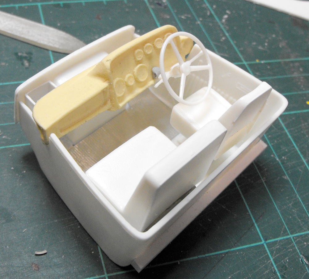
Dry run of the cabin bits and pieces. The dash casting is a bit rough and I'm worried how well it will come up. We'll see.
The internal blanking plates from the front guards are no longer needed, so they were cut through by scoring with the back of a hobby knife.
Like this.
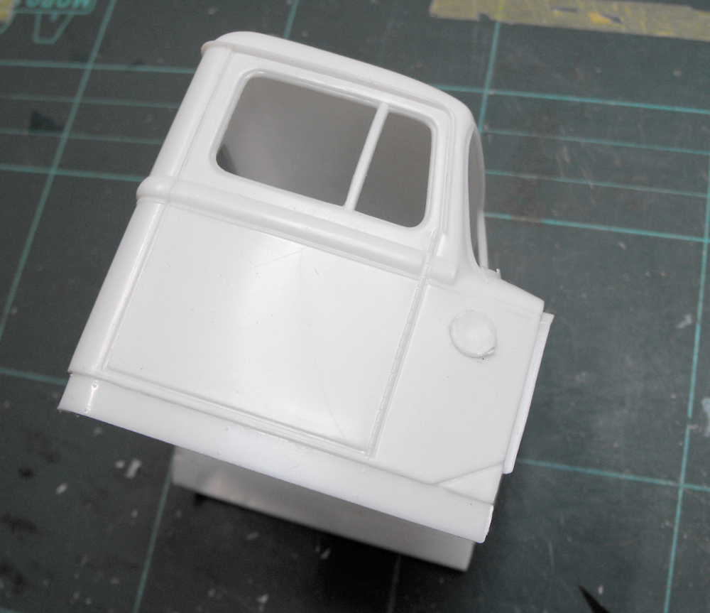
The cab skirts were added and the old oil cooler hole plugged.
The radiator has a metal sheeting suround added. I'm not at all sure why when it was operating in Viet Nam where you certainly wouldn't have needed baffles! There were also some strengthening ribs added.
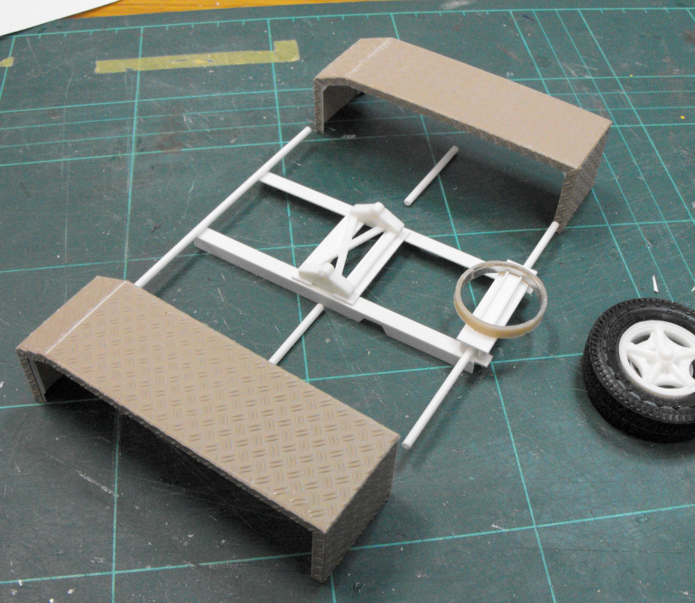
On to the chassis subframe. As I mentioned before, It turns out I know the chap who engineered the subframe and guards! Under his direction, I fabricated up the frame and guard supports and the spare carrier. He pointed out something interesting: It doesn't look like the spare, if fitted to the carrier, will fit under the nose of a trailer. I'll have to see as we progress.

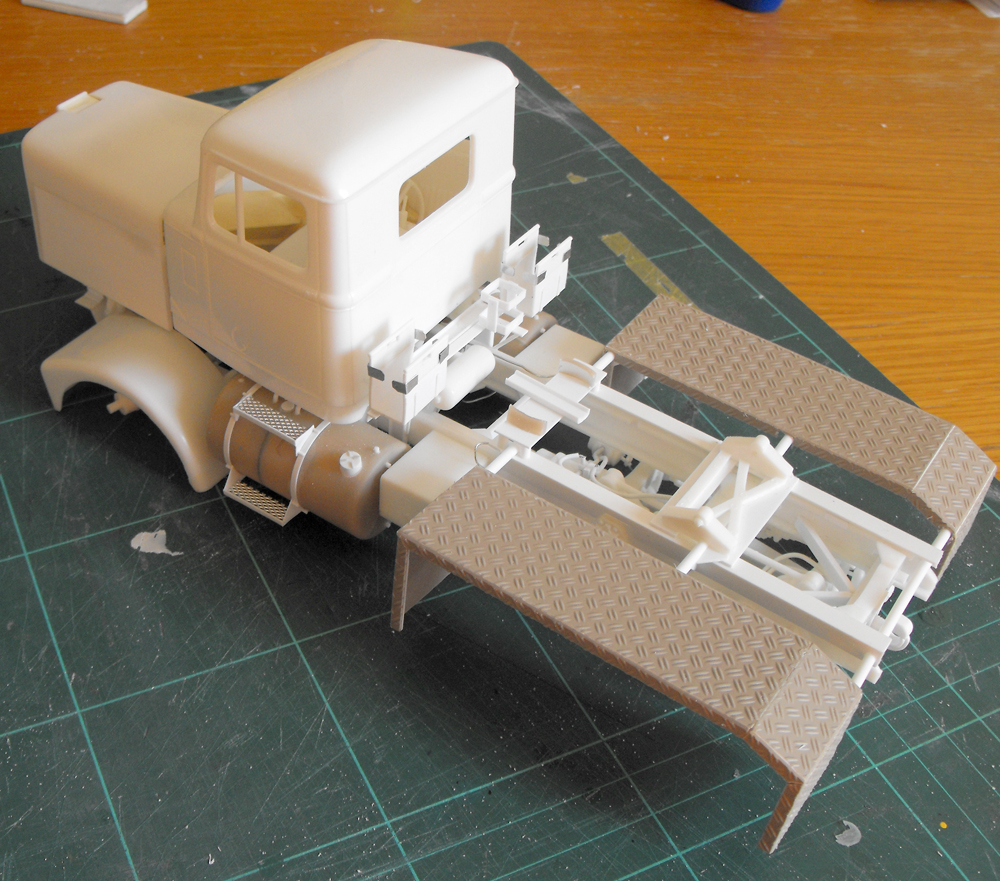
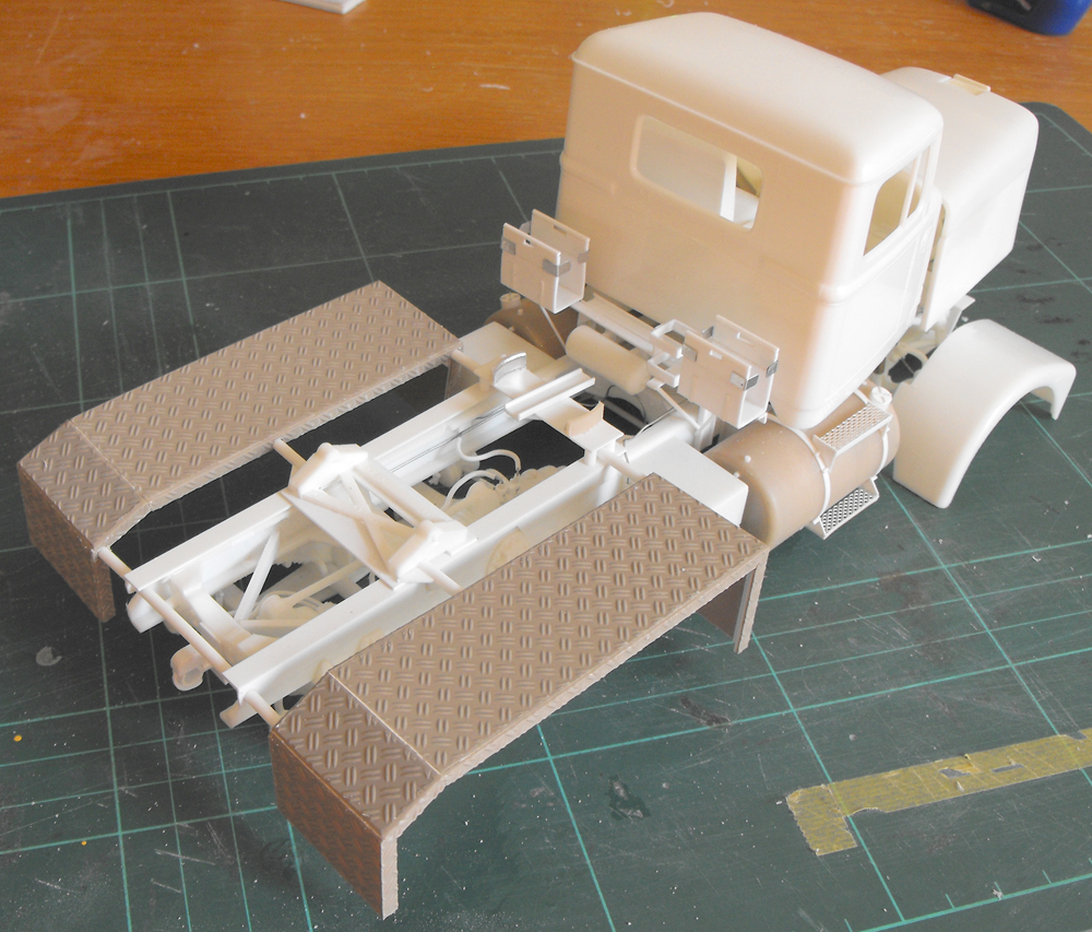
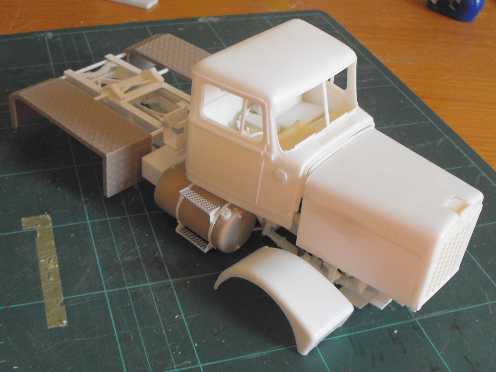
Time for another dry run. Here are the engine, hassis, radiator grille, bonnet, front guards, rear guards, and interior resting together. It looks like it's almost time for some paint!

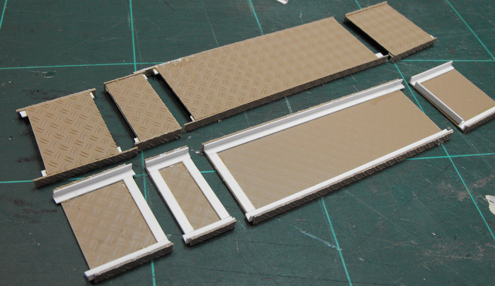
While some glue cures, I've pulled out the trailer kit to make a start on that. That single-piece deck is quite a monster. It'll give a good solid base. There are minor mods to do to the trailer including adding tie-down rails and rearranging the tail end. I'll also scratch up some cages.
Go to Scale Modelling page from Diamond Reo Model
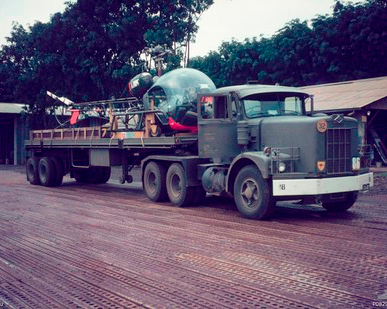 Here's what they looked like in SEA service.