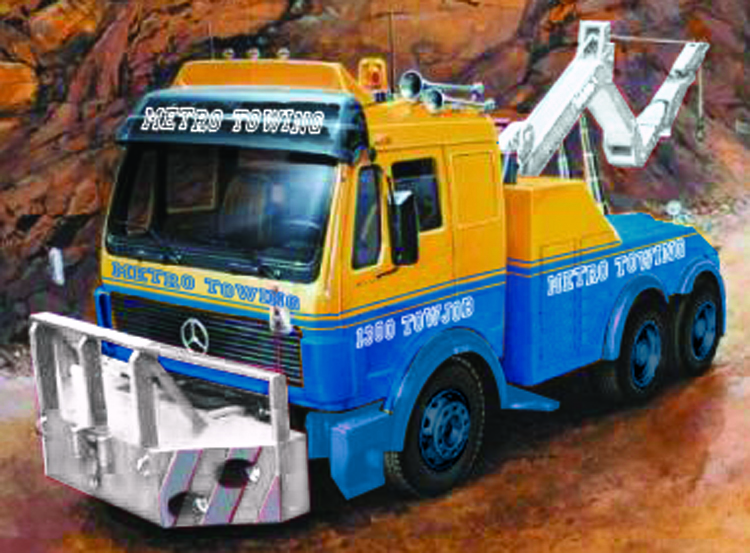
1:24 Italeri ITA 3808
Mercedes Wrecker
Build Log
The Kit
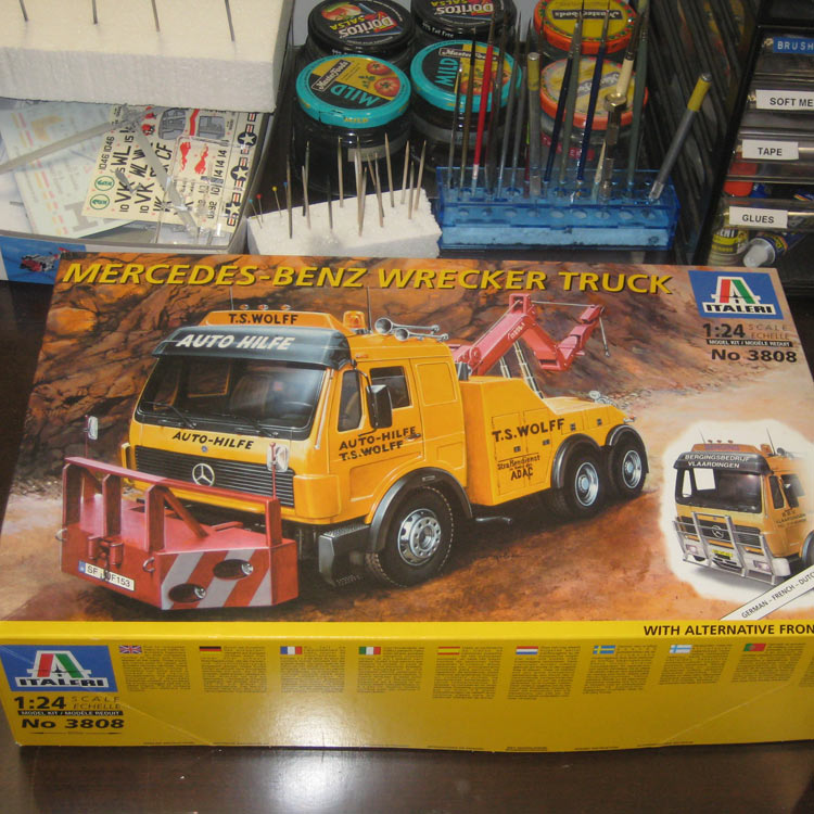
The kit box.
As far as big scale truck models go, there have only ever been a few players in the game. In the early days we had AMT with their relatively crude offerings. ERTL then showed up with kits that were a significant improvement on the AMT Offerings. The third big player in the field has been Italeri. Italeri has brought their usual flair to the truck subjects, producing highly detailed well engineered models that are often moulded in several colours. I’ve even seen built examples of these models that were not painted at all, weathering had simply been added over the raw plastic, and they were still very convincing.
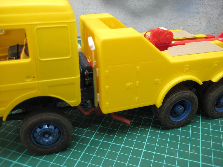
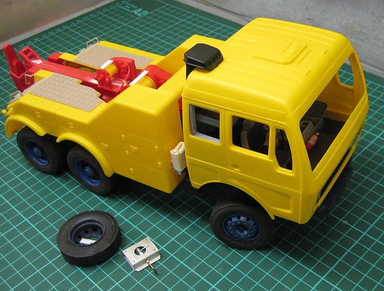
The subject of this build is their Mercedes Benz Wrecker, kit #ITA 3808. This kit comprises most of the sprues from their Merc 2238 prime mover kit along with the bolt-on wrecker body they have used in many their other tow-truck kits.
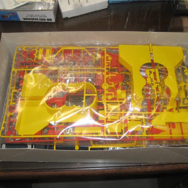
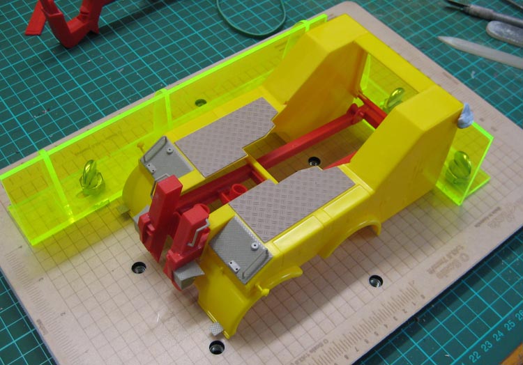
The rather bright plastic will certainly need priming!
My own aim for this build is to get some experience with airbrushing and, in particular, gloss paint finishes. That’s apart from the fact that I like subjects that appear to have mass.
CONSTRUCTION
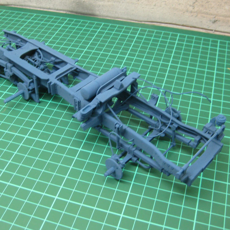
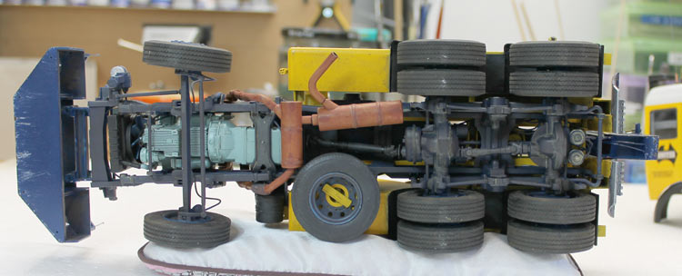
Chassis and running gear.
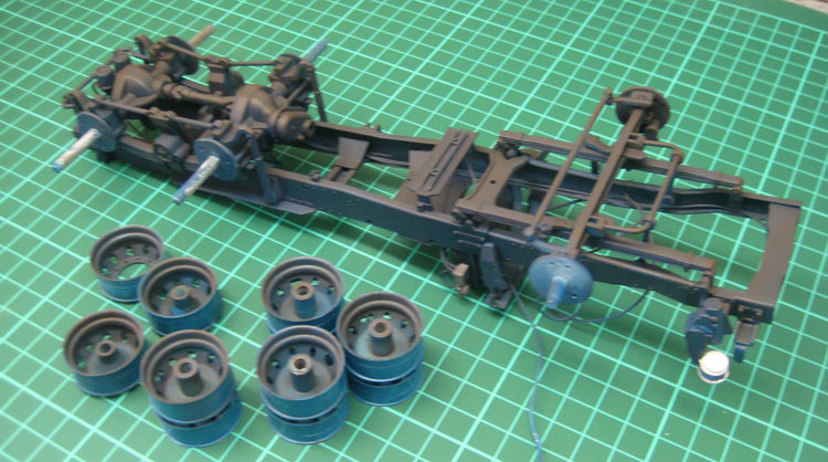
Construction starts with the chassis and suspension The chassis is made up in the usual way of separate chassis rails and cross members. Some of Italeri’s later offerings are kerbside models hat have the entire chassis, sometimes even including the fuel tanks, moulded as a single piece. Not so this beast, so care has to be taken to keep the chassis rails parallel. Construction of the chassis is straight forward, though I must say here that the instructions can be a bit vague on part locations. There is also an indication on the instructions that the chassis rails need to be shortened, but it is not clearly shown where to cut. I’ll wait until the wrecker body is ready to attach and see if it fouls anywhere.
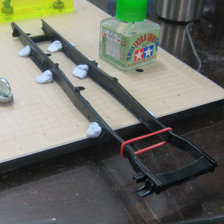
The chassis rails were secured to a nice flat surface while the glue cured.
The front wheels are designed to be steerable. The instructions indicate this is to be done by heat-squashing some axle pins. I prefer to carefully glue a slice of tube over the pin end instead. I find this a neater and more elegant solution.
I will be adding some extra detail in the form of air hoses and fuel lines as I go.
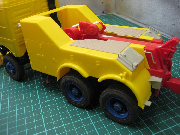
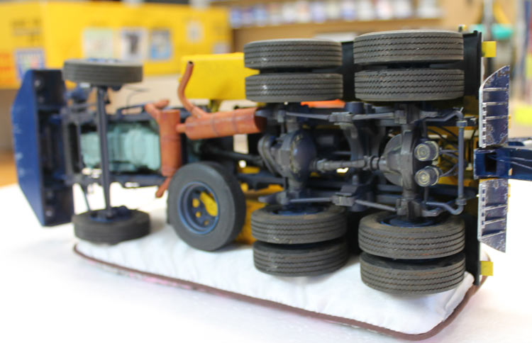
This truck is a bogie drive, which is a rarity on Euro trucks. It might be something to do with axle loadings and tight windy streets. Anyway, the bogie was assembled and set up on parallel rails to make sure all the wheels would touch the ground at the finish line.
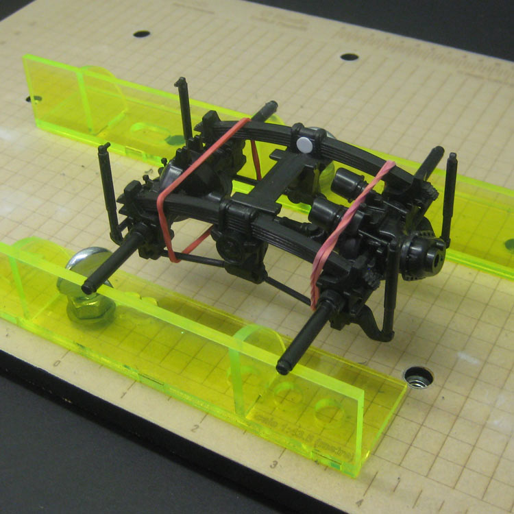
The bogie drive getting the trueing treatment.
Even though the Italeri kits are well engineered, I find there is always a lot of cleanup needed on the mould part lines. This kit is no exception. Quite a lot of the build time has been spent scraping and sanding parts prior to assembly.
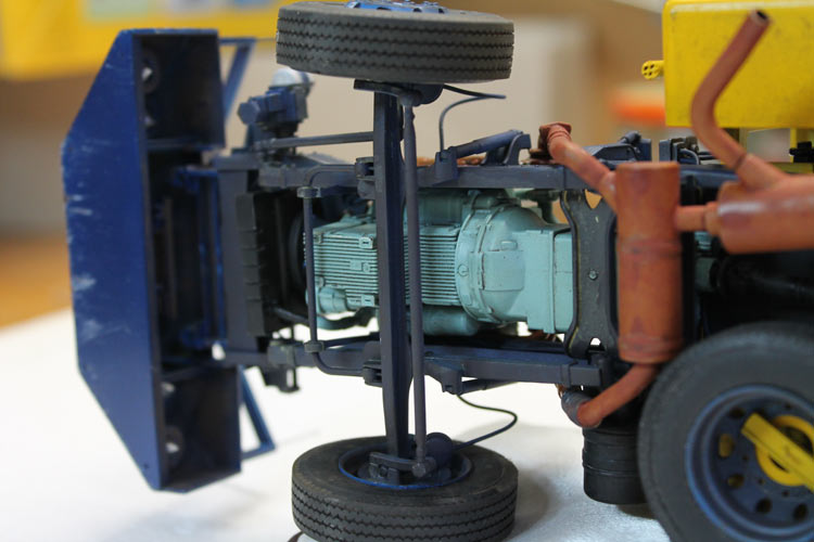
Engine and Transmission
I added a piece of aluminium expanded mesh to the inside of the radiator fan shroud so it didn’t look so hollow.
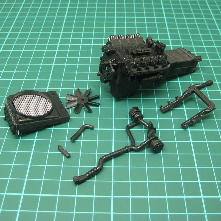
Basic power plant assembled with mesh added to rear of radiator.
These items go together easily after a bit of a clean up. The whole assembly sprayed with Citadel Skull White primer out of the spray can.
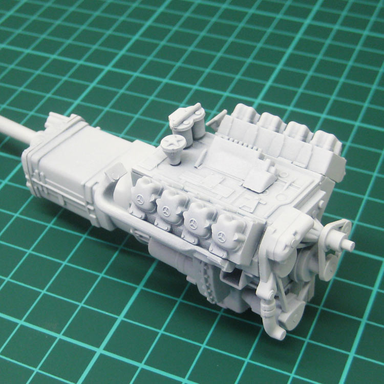
Engine and gearbox have been primed with Citadel Skull White from a spray can.
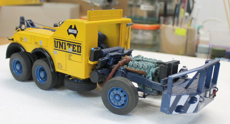
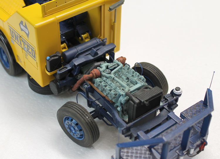
Fuel injector lines were added with fuse wire and the assembly topped off with Valejo Air RML65 green. This is a reasonably good match for the MB diesel colour. This is the first time I have used Valejo paints and I am impressed. They airbrush beautifully and also brush extremely well.
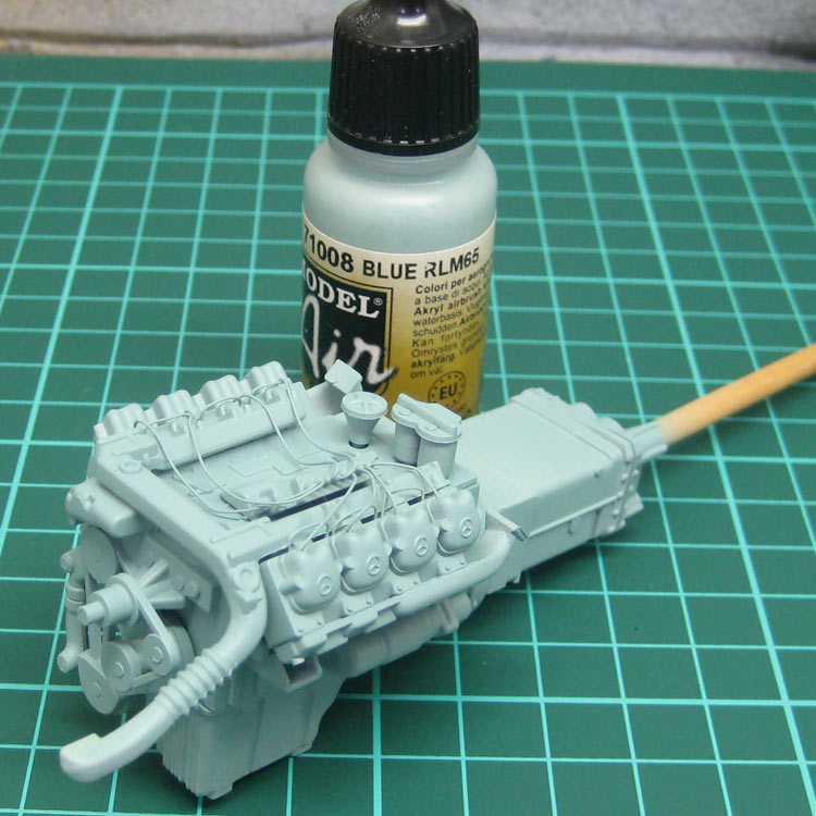
Fuel injector lines have been added and the whole lot airbrushed with Valejo Air RLM65
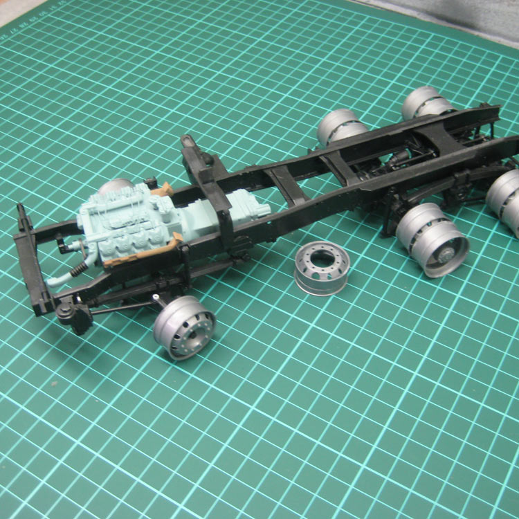
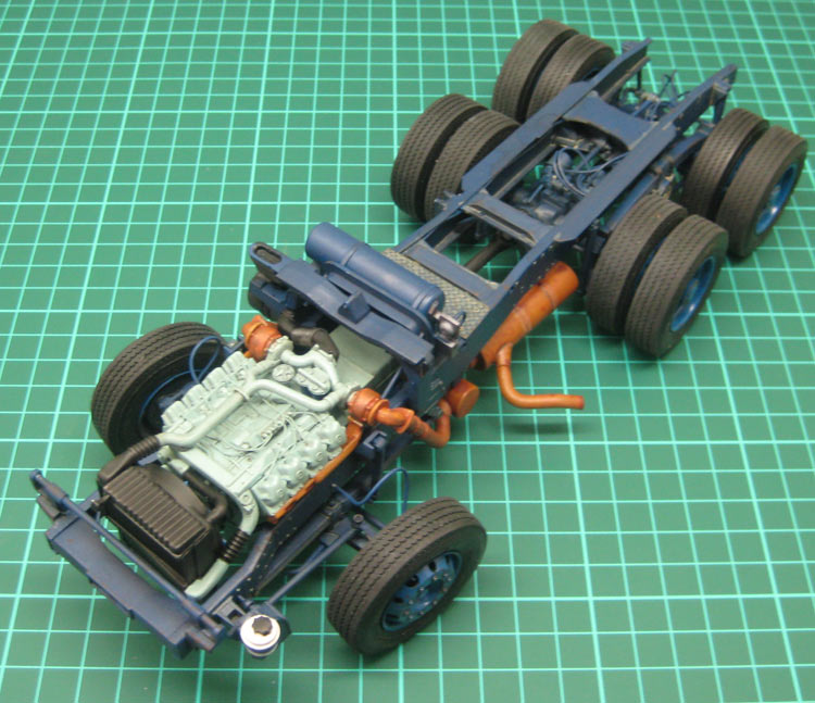
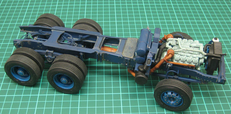
Dry run of the chassis and powertrain showing the discs glued to the steering pins.
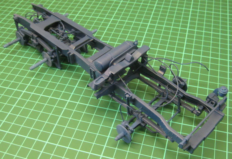
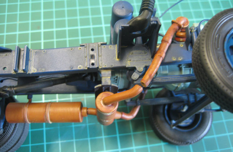
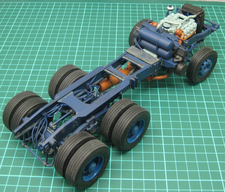
I wanted to busy-up the chassis a bit. Trucks always seem to have a lot of wiring and plumbing going on and the bare chassis was looking, well, bare. It was at this point I discovered the kit doesn’t use fuel or air tanks. I guess the wrecker body takes up the space they would use. I wonder where they are fitted on the prototype? I fitted the air tanks from the kit behind the cab. No fuel tanks were supplied at all. I added a couple of nondescript blacks of plastic as valve gear and ran electrical wiring as air hoses. I like using electrical wiring for this, rather than fuse wire, as the electrical wiring has a spring to it that simulates airhose nicely. Looking at the model now, I should probably have gone for a narrower wire. It looks a bit over-scale.
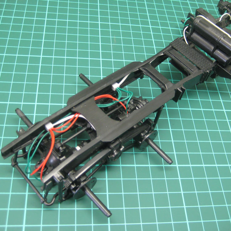
Air lines installed and air tanks added behind cab.
I needed to finalise the colour scheme now so I sat down with Photoshop and worked out a simple scheme that would lend itself to some home-made pinstripe decalling and not require any masking. This meant the cab and body had to be white so the translucent decals would show up well. Cab and body will be white, chassis dark blue and wheels, bumpers and crane will be a nice teal blue, Revell 51.
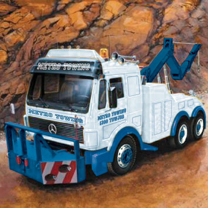
The intended colour scheme.
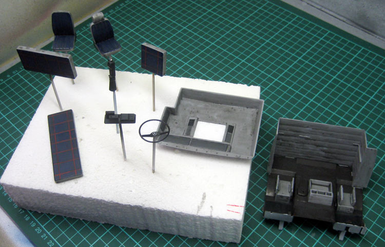
The completed chassis was then primed using the Skull White spraycan and some pre-shading applied.
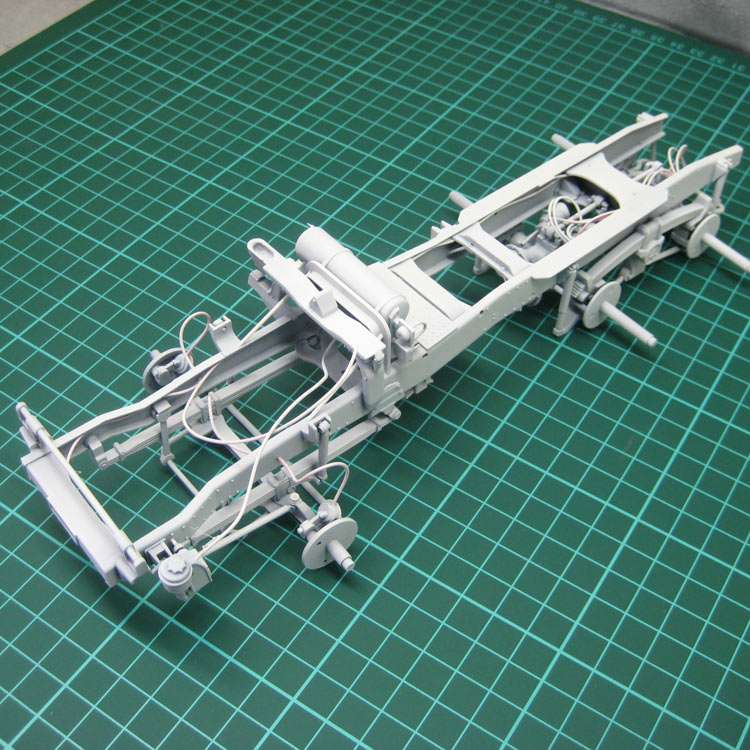
Chassis primed with Citadel Skull White straight from the spray can.
Preshading airbrushed in black.
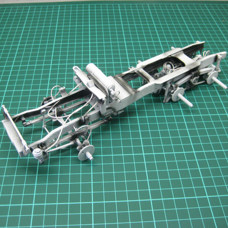
I picked a Valejo Air dark blue, but it turned out to be a translucent colour (oops!) so I then topcoated the whole chassis with Tamiya XF-8 dark blue flat acrylic. This obliterated the preshading. Oh well.
Chassis after airbrushing with Tamiya XF-8 Flat Blue.
The entire chassis was then sprayed with a generous coat of Testors Modelmaster Metaliser Sealer in preparation for some grunge. This darkened the Tamiya blue a whole lot. I'll need to remember that! This is BEFORE the grunge wash.
Chassis prepped for washes and grunge.
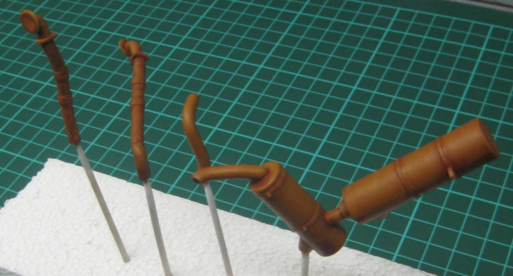
The exhaust components were assembled at this stage and primed and painted brown in preparation for some Rustall. This is the first time I’ve used Rustall. I possibly should have painted it over black instead of brown.
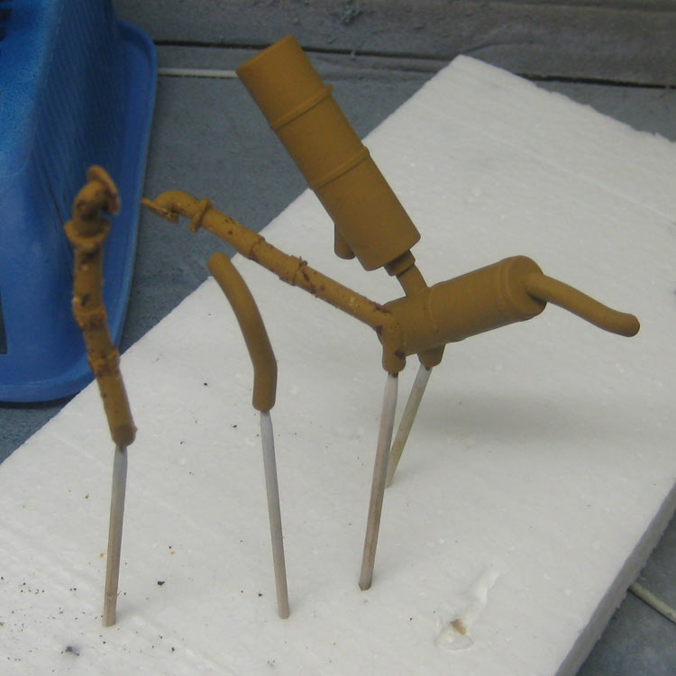
In the beginning ...
I’ve applied probably 10 or 20 coats of Rustall red to get this result. The dark spots are bits of pastel I was experimenting with to try and add texture.
... half way ...
Wheels and Tyres
The wheel rims were cleaned up and glued together and then primed with the Citadel Skull White as well. Revell #51 gloss blue was then used as the topcoat. Tyre treads have been scuffed up to indicate some wear, too.
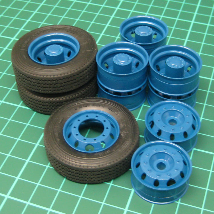
Scuffed tyres along with wheel rims in pristine state.
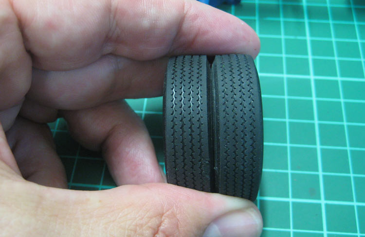
Shiny tread be gone!
Scuffing up the tyre perimeter is all good and well, but when you look into the tread pattern, you can still see nice and shiny plastic! I fixed this by dragging a dental probe around the tread grooves until the shininess was removed.
.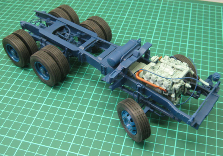
Another dry run.
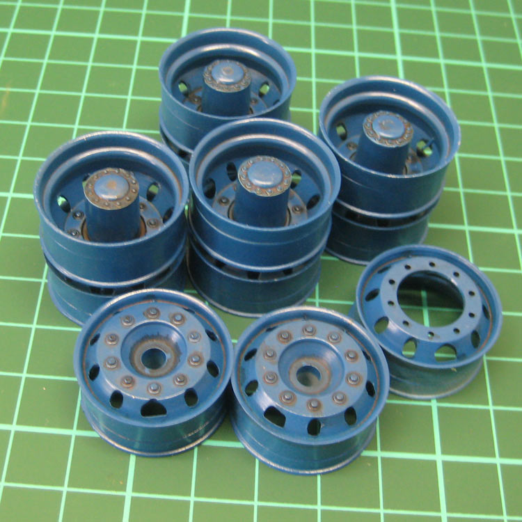
A spray with some thinned Valejo 70.822 German Cam. Black Brown gives a good representation of road grime.
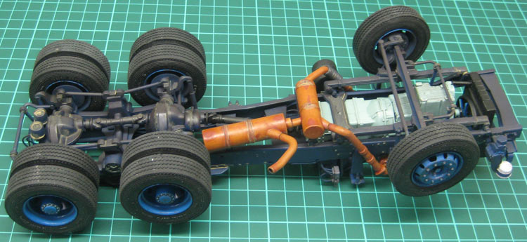
With all the strangely shaped parts that have to come together to create the exhaust system, some misalignment might have been inevitable (for me, anyway). There was a 2mm gap between one of the downpipes and the muffler attachment. This was remedied by creating a flexible join section with brass wire wound around the existing pipe and then slid down over the join.
The misalignment of the exhaust parts. Floquil mud pinwash is seen here, too
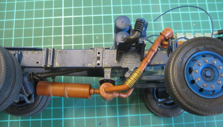
The solution to the exhaust issue was to wrap some brass wire around the long exhaust section and slide it down to cover the gap. This gives the impression of a flexible exhaust joint.
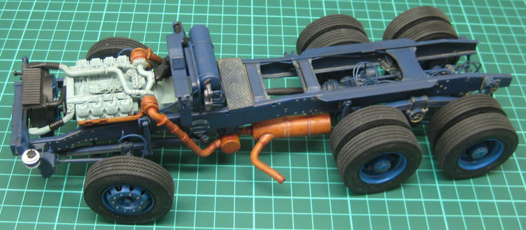
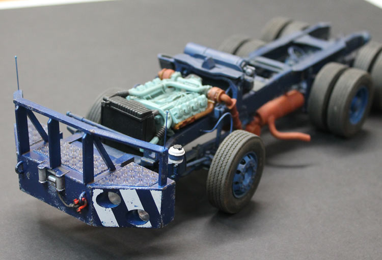
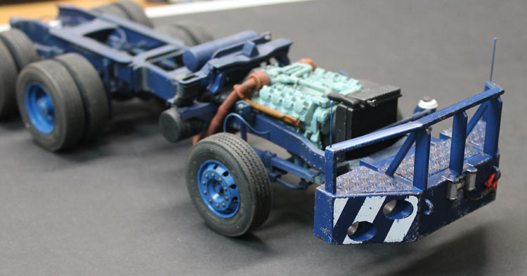
I think I’ll call the chassis / drive train done. The engine looks more grungy in the flesh.
At this point I attached all the remaining ancillaries, tucked the wire ends out of sight and glued on the wheels and tyres. Some more weathering was added with pinwashes of more dust and oily grunge to bring the differing tones more into alignment. The whole shebang will probably get some dust overspray later in the build, but for the time being, I'll call the chassis done!
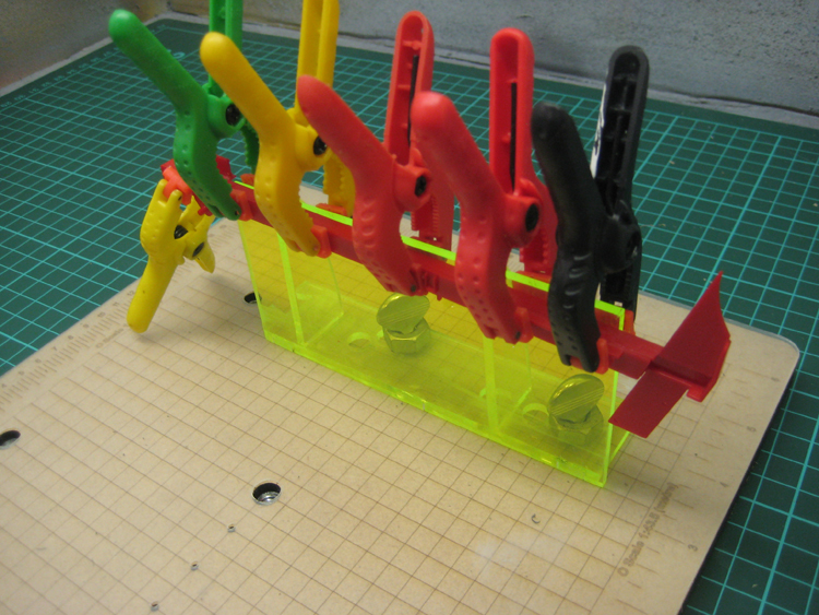
The radiator and associated plumbing took some serious test fitting and even after that I had the lot bound up with rubber bands and clamps for two days while the glue set.
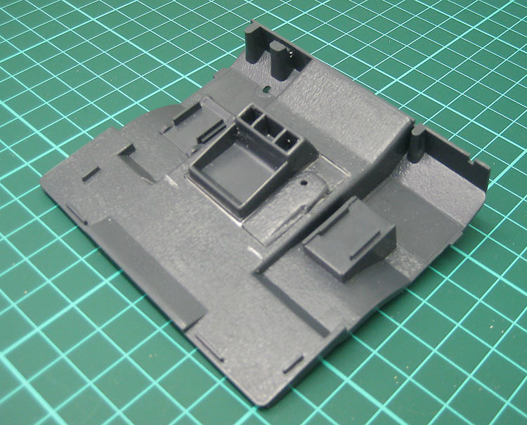
Cab Interior.
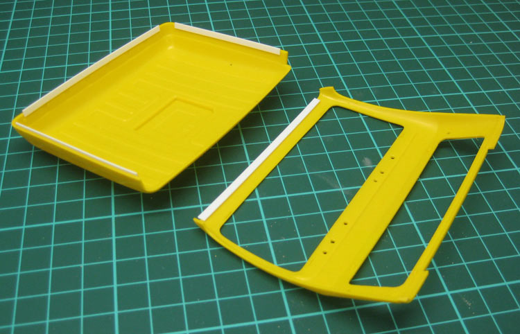
The Italeri kit is, understandably, LHD. Looking at the kit parts, I decided it wouldn't be too hard to swap it over. The European trucks seem to have been designed with this in mind and they lack the "handedness" of, particularly, the US trucks. I will conveniently ignore the fact that I have already added the steering box to the left side of the chassis.
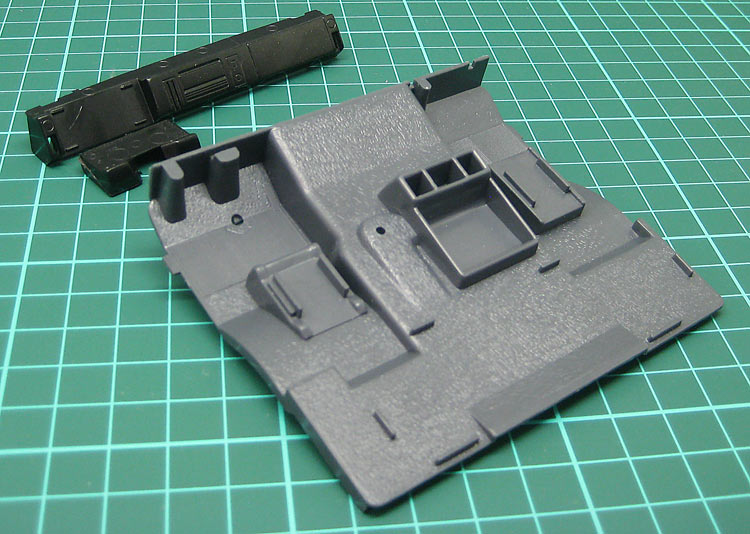
The kit parts that will need to be altered to make the model RHD including the floor pan and dash.
I used some old Dymo tape as a straight edge and used a dental pick to score through the kit part.
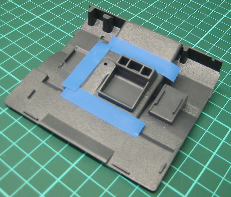
Using Dymo tape as a straightedge.
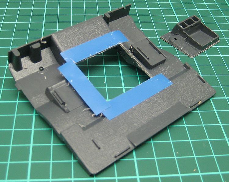
The centre console and gear shift bulge removed.
A scrap of plastic card will serve as a new floor for the re-arranged console parts.
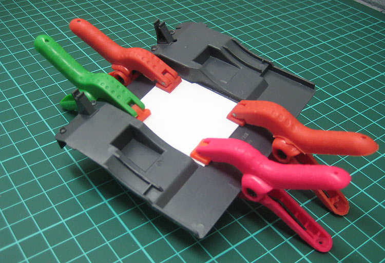
A new plastic card floor.
The centre console and gear shift bulge were then separated, reversed and glued to the new floor. The gaps were filled with white glue. I wasn't going to try and fill and sand this join due to the tight confines and the texture of the carpet. I'll just make it look like separate pieces of carpet.
The replaced console parts.
I was looking at cutting and re-arranging the dash, too, so I strengthened it with a new plastic card back.
New plastic card back on the dash.
In the end I decided against trying to get a clean cut and shut or trying to build a new glovebox. Instead I scratched up a fictional comms panel with a couple of two-way radios and some kind of despatcher / blue-force-tracker / navigator / microwave oven.
Back to the Future comms panel.
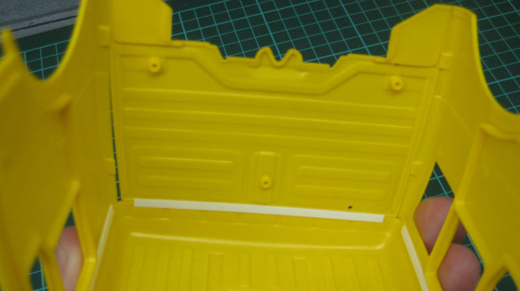
The seats and beds all have hollow backs, so some plastic card was employed to fill the gaps.
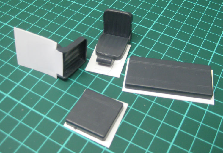
Filling in the hollow-back parts.
With the major construction done on the interior it was off to the spray booth for a hit of primer. I'm using Citadel Skull White primer from a rattle can. It seems to be pretty robust and reasonably opaque.
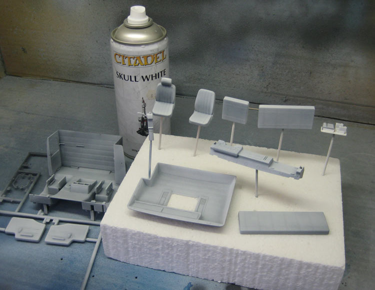
Priming the cab interior parts.
The interior parts were sprayed with a Valejo Air light grey and then colours were brush painted with Valejo acrylics. These brush on reasonably well, but I still ended up with a lot of brush marks. I'll mask and spray next time.
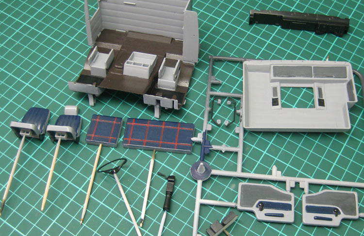
A bit of colour thrown on inside.
The interior parts were tacked together for a dry run to see how they all worked together. Nothing special, but it'll do the job.
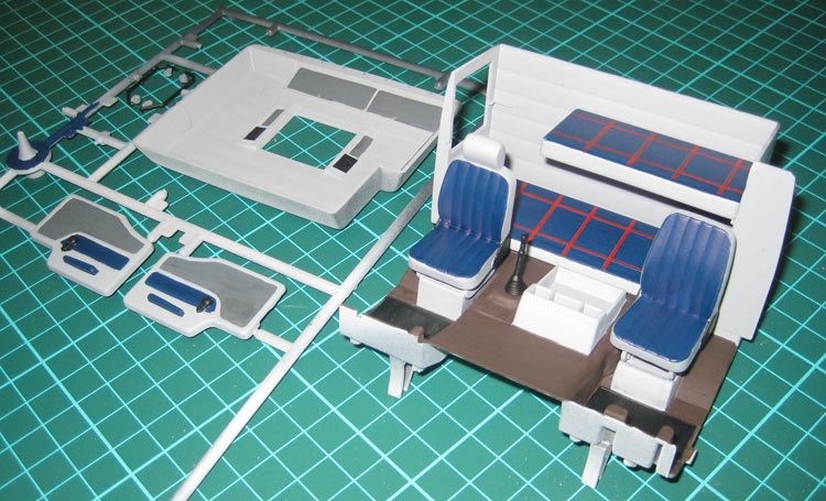
Dry fit of the interior parts.
I hit the interior parts with some Promodeller weathering washes. This is the first time I have used these and the jury is still out. The washes are water based and the concept is that you slosh them on quite liberally and then wipe back the effect with a SLIGHTLY damp piece of paper towel. The idea is that you wipe off progressively more until you are happy with the level of grunge. I am using them over satin acrylics here and they are tending to be a bit "all-or-nothing". I'm finding they are wiping right off or leaving clear demarcations between the wiped and unwiped areas, even when I use the bare minimum of moisture to wipe. They do work very well as pinwashes, though. They flow beautifully and are surprisingly subtle.
Priming the cab interior parts.
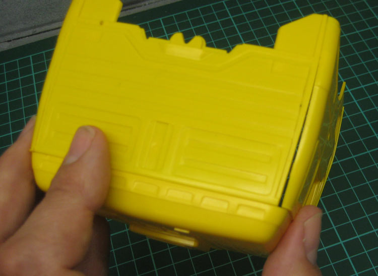
I really want to assemble the cab before I paint it. It looks like this will be possible with one small alteration. There are to protuberances poking into the interior space from the cab back wall.
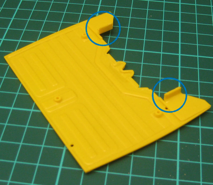
The back of the cab showing the protuberances.
I figure I can lose these, the cab interior will slide in nice and easy and no one (except you, dear reader) will be any the wiser!
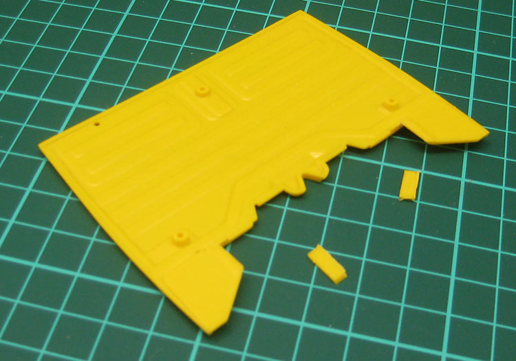
The cab rear after a a generous application of "Protuberance-be-gone!".
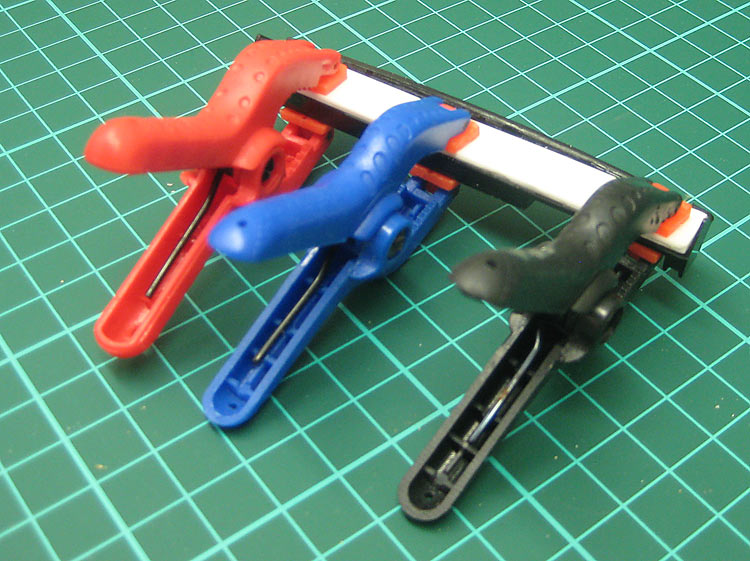
On to the assembly of the cab. I'm using the Brunel Hobbies right-angle building device as a guide here. The cab parts themselves are too curved to be clamped square against the uprights. This is enough to keep the top of the cab square and level and the walls true.
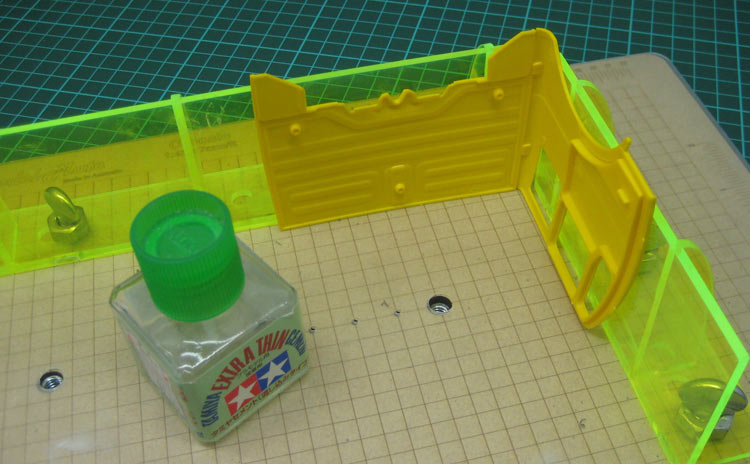
Aligning and glueing the cab walls.
There's not a lot of surface area to glue to on the cab parts. I wanted to be sure the bond was good and solid for when I slide the interior in. I don't want to have to redo the cab paint. I applied reinforcing strips of styrene along the interior edges of the joins where they will be invisible. I find I do this with all similar joins . I like the reassurance it gives me that the join will stay rock solid through any filling and sanding required.
Reinforcing strips on the cab joins.
Fail! I didn't pick up that the insides of the walls don't align with the insides of the roof. A dry-run presented this problem: A walls don't meet the back.
The gap at the back of the cab.
The solution was to shave off the strengthening strips back to the mating edge of the roof and glue new strips on top of the old stubs. This brought the walls in just enough to fix the problem.
The back of the cab showing the protuberances.
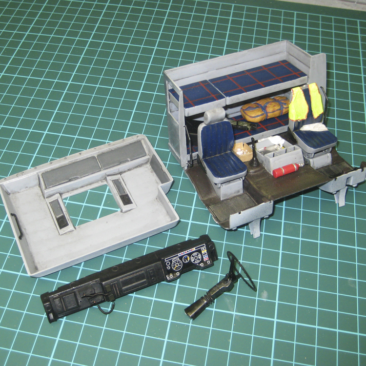
Meanwhile, the interior is taking shape on another corner of the workbench. Bits and pieces have been painted and added including a kit bag, cardboard box, alloy clipboard, fire extinguisher, water jerry can, papers, rags etc. Over the back of the passenger seat can be seen a safety vest made from copy paper. It was cut to shape and then soaked in a water amd white glue mix. Once saturated and flimsy, it was draped over the seat.
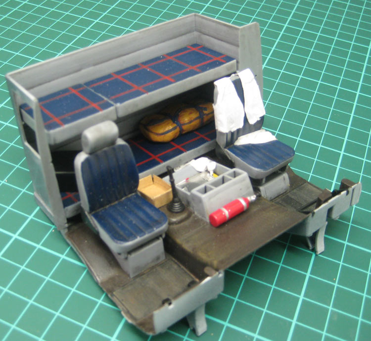
Details added to the interior.
I used paper for the safety vest so I could use a highlighter to colour it!
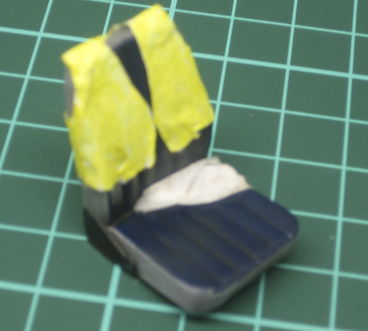
Paper safety vest after being hit with the highlighter.
All the interior components are pretty much finished now. Grunge has been added, curly mike wire and mikes are added to the radios, dash decal is on (It really didn't match the dash moulding, by the way).
Interior pretty much done.
To add abit of interest to the underside of the cab, I cut up some biscuit-tray plastic and glued it in place to replicate sound-deadening/heat-shield material. Glueing it on was a bit of a struggle as it is a high-oil content plastic and there's not much contact area due to the patterning. Regular styrene cement didn't work and double sided tape didn't stick to it. I ended up using a pool of superglue and clamoing the shapes down for 24 hours. It seems to have worked.
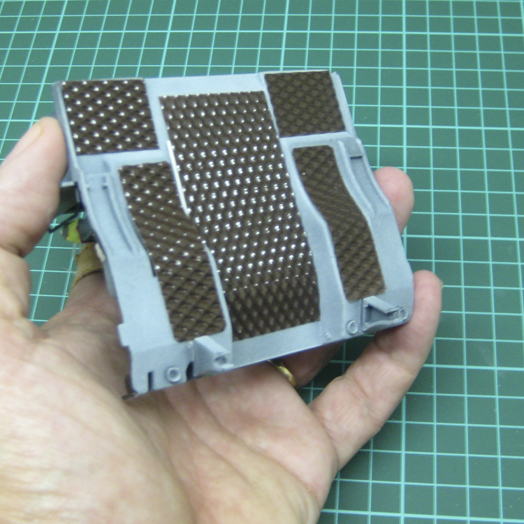
Biscuit tray soundproofing.
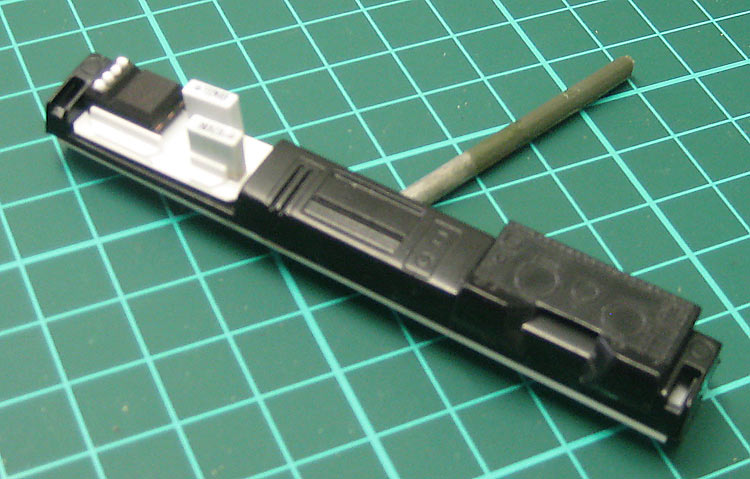
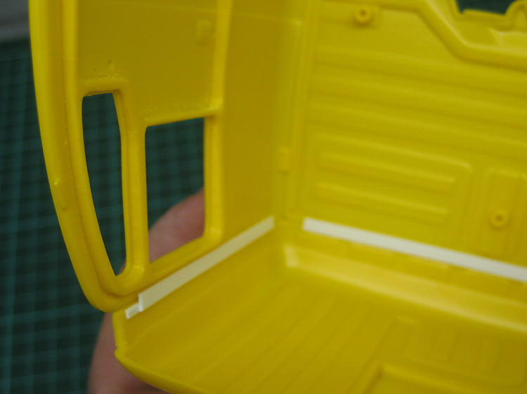
One issue that arose during dry-runs is that there is a significant gap between the cab side window and the interior shell. I blocked this area in with some square styrene rod that I then filed to shape.
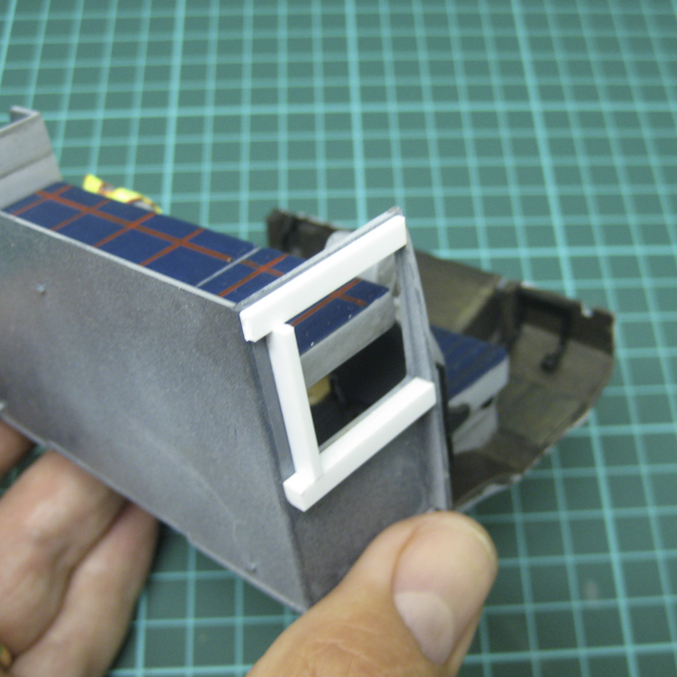
Styrene blocking in place ....
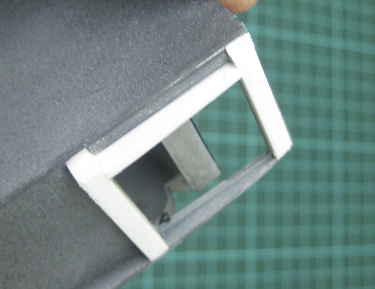
... and filed to shape.
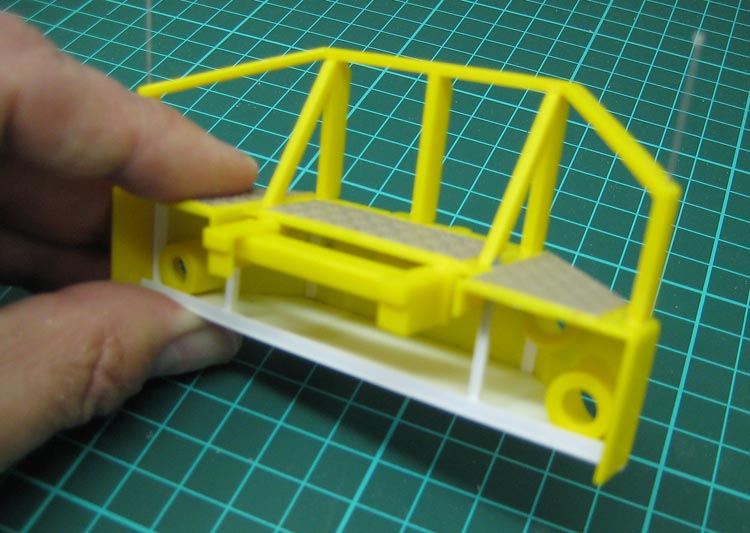
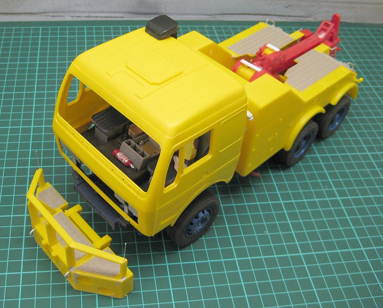
Big Bumper.
On to the next subassembly: The big bumper. I decided to use the big bumper as it adds so much character to the truck and makes it look heavier. The component parts were cut off the trees and arranged. Notice how the entire top frame is one part. This eliminates most alignment problems.
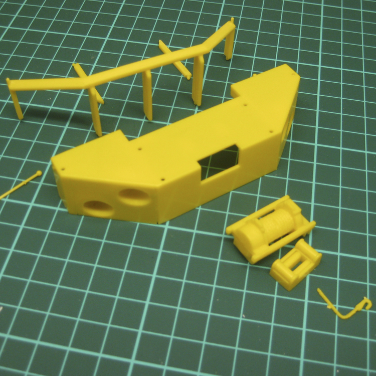
Components of the big bumper.
There was a small gap around the headlight insert panels on the bumper that needed a little filler.
Filling the seam on the bumper inserts.
The headlights supplied in the kit are simply flat, round clear discs with some lense detail that are supposed to glue into flat recesses in the bumper. These seldom look any good, so I have drilled out the recesses and I'm now looking for something 8mmØ that looks like a headlight reflector.
Headlight recesses drilled out.
To dress up the bumper a little I thought some teadplate might be in order.
Treadplate for the bumper.
I thought I might try a technique for weld seams I've seen armour modellers use. I stretched some sprue with my trusty heat gun (I much prefer the heat gun than a naked flame. The heat gun softens a larger area of sprue, too.) and cut lengths to fit the edges of the treadplate.
Stretched sprue section for the weld seam.
This was then glued in place with Tamiya very thin liquid cement. The glue softens the stretched sprue and you can then press a dental probe or similar into the stretched sprue to create a weld bead texture.
Stretched sprue glued in place. Other weld beads here have been finished
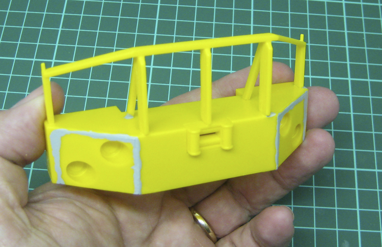
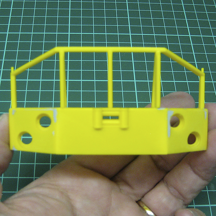
There are two flimsy looking towing eyes provided in the kit for the front of the bumper. I replaced these with some nice solid units created from some thick armature wire from the craft shop. The railing part came with molded-on corner markers / mirror stands. These were fragile and broke quite quickly. I've replaced them here with some high-tensile wire with beads of superglue on the tips.
I've been hunting around the craft shops for ages to try and find something to replace the kit bumper lights. All you get in the kit is a lense that is supposed to glue onto a flat surface that you have painted silver. Not very realistic. I was searching for beads or sequins or rhinestones that would do the job, but to no avail. The rhinestones were closest, but they still just looked like jewels. Then I struck on the idea of making a reflector out of thick foil. I made one and popped it in and I think it will work well. I'll detail that procedure a bit later in the build.
New towing eyes, corner markers and a test headlight reflector.
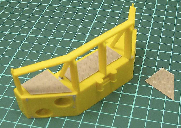
Body and Towing Crane.
With the bumper now taken as far as I will before painting, it's time to start on the rear towing body. This starts with the crane assembly. The parts were quite badly warped, so I clamped them to a nice flat surface after gluing.
One of the warped side rails clamped to a former to try and straighten it.
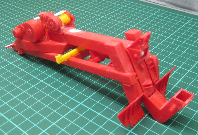
The crane went together pretty much without a hitch (Ouch!).
Nothing out of the ordinary with the assembly of the crane / lift mechanism. Glueing, clamping, filling, filing and sanding as per usual..
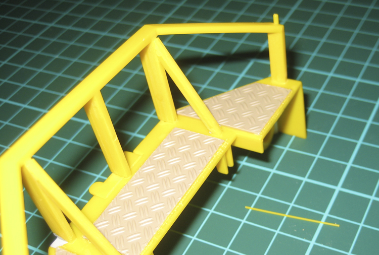
The rear body was fairly straightforward, too.
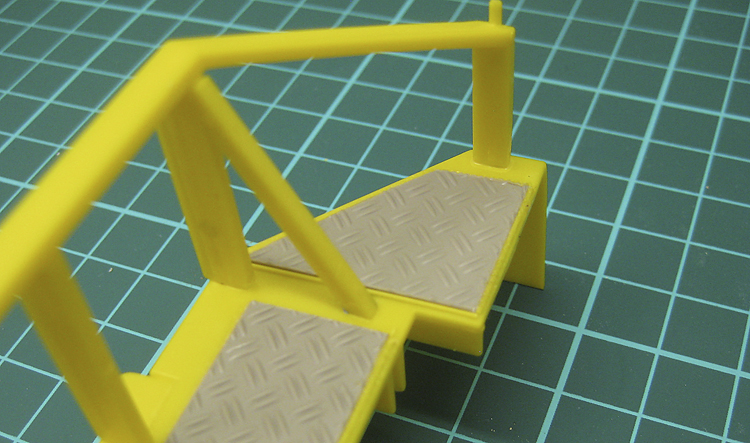
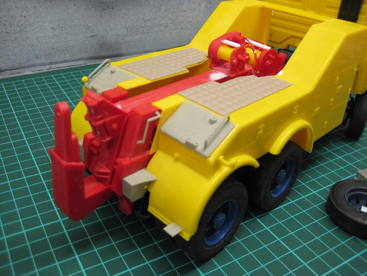
I have a general dislike of chrome plated parts. I find they seldome look realistic. There were some steps and treadplate in the kit that were chromed, along with some grab rails. I stripped the chrome with oven cleaner and assembled the parts as per the instructions. Italeri don't give you an option for showing the lift in its lowered position, they just have some fully extended rams. I reckon this looks a bit awkward, so I'm going to leave it resting on the lower frame, rather than stuck up in the air. To add a bit of character to the body, I cut some more sections of treadplate and glued them to the top of the body. I have no idea if there is any reason to ever go wandering around up there, but I like the look.
I'm still undecided about the colour scheme. The old one just wasn't grabbing me any more. I want something with abit more detail and interest. Maybe this.
Possible new colour scheme. Still thinking about it...
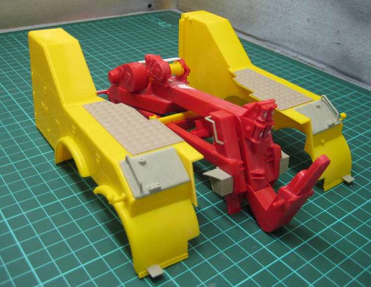
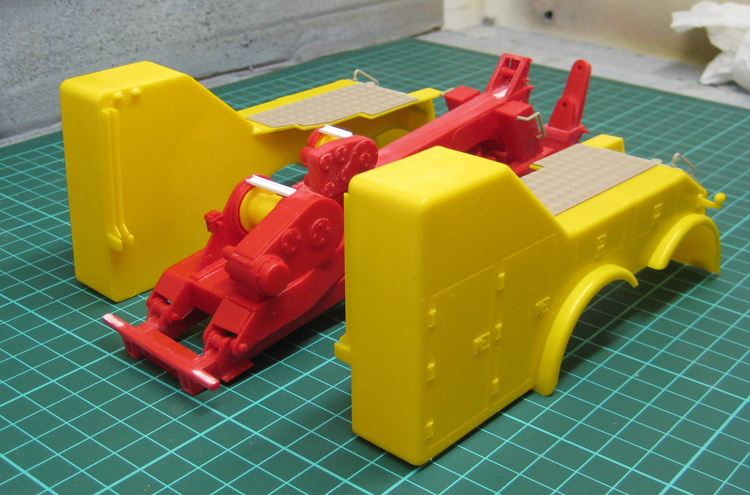
I've decided to make the body and subframe the same colour, so I can nail these parts together now and not have to worry about paint and glue joins and stuff. This took a bit of coaxing and there was a fair bit filed off a few of the underside parts before I was satisfied it was going to be an unstressed structure. You can see the de-chromed parts attached here too.
Body parts being trued up on The Rack.
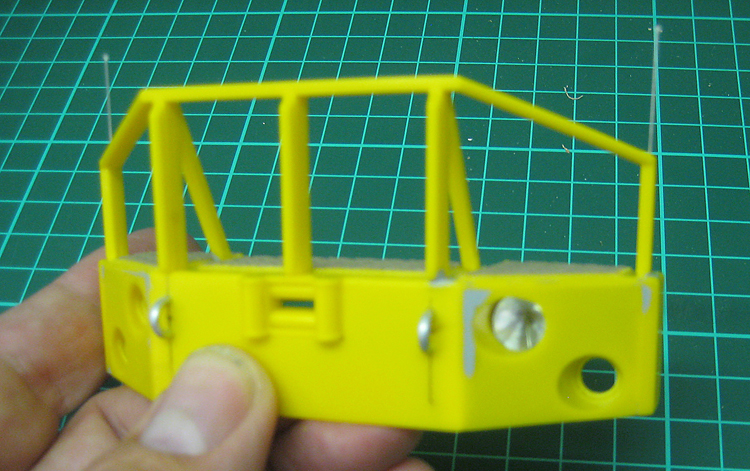
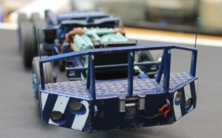
Straight out of the box, the big front bumper is hollow and made of quite thin parts. Considering this is supposed to be a counterweight to increase the lifting capacity and is also used as a buffer, it's not very convincing. I added a base to it and some internal bracing to give it a heavier feel. At least now you can't see the thin walls.
Detail has been added to the underside of the bumper.
The subframe and body were looking a bit bare so I added some hydraulic lines for the rear spades, boom lifts and winch drums.
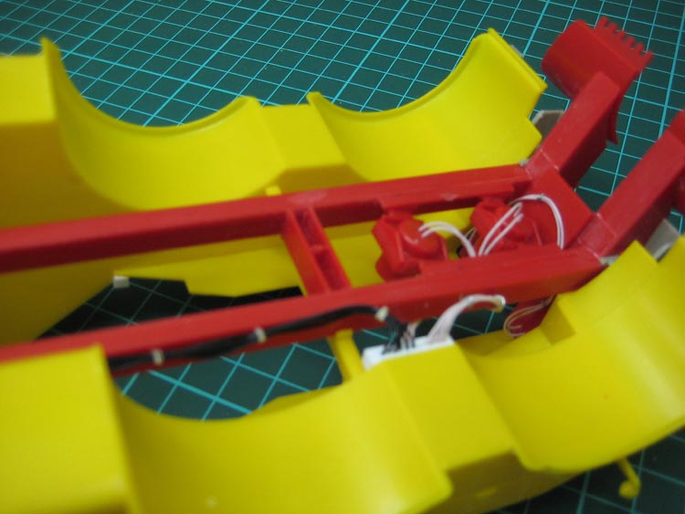
Underside of the subframe showing some added plumbing.
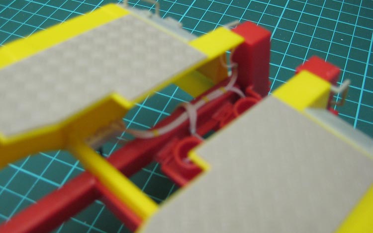
More plumbing.
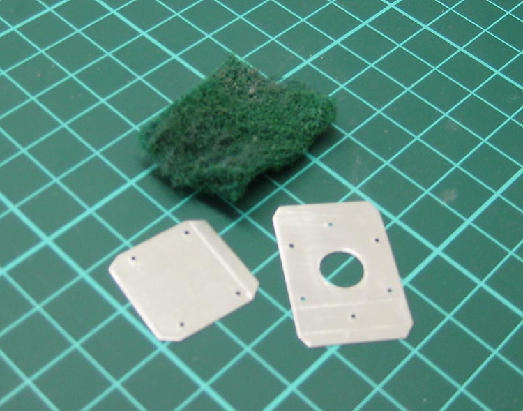
Having decided to sling the spare wheel under the bodywork, I needed a way to do it. I designed a basic hoist mechanism that I could make up out of sheet metal.
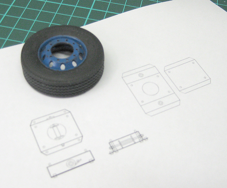
Spare wheel and wheel-hoist drawing.
I found a great source of sheet aluminium at the hardware shop recently. There is an aluminium flashing product called Weatherflash. It's a 99% aluminium sheet that about three times thicker than coffee tin seal. It is very maleable and easy to fold and will cut with a pair of stout scissors. It's cheap, too. $16 bought a 10 metre roll, surely a lifetime's supply!
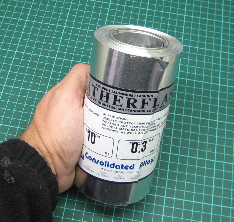
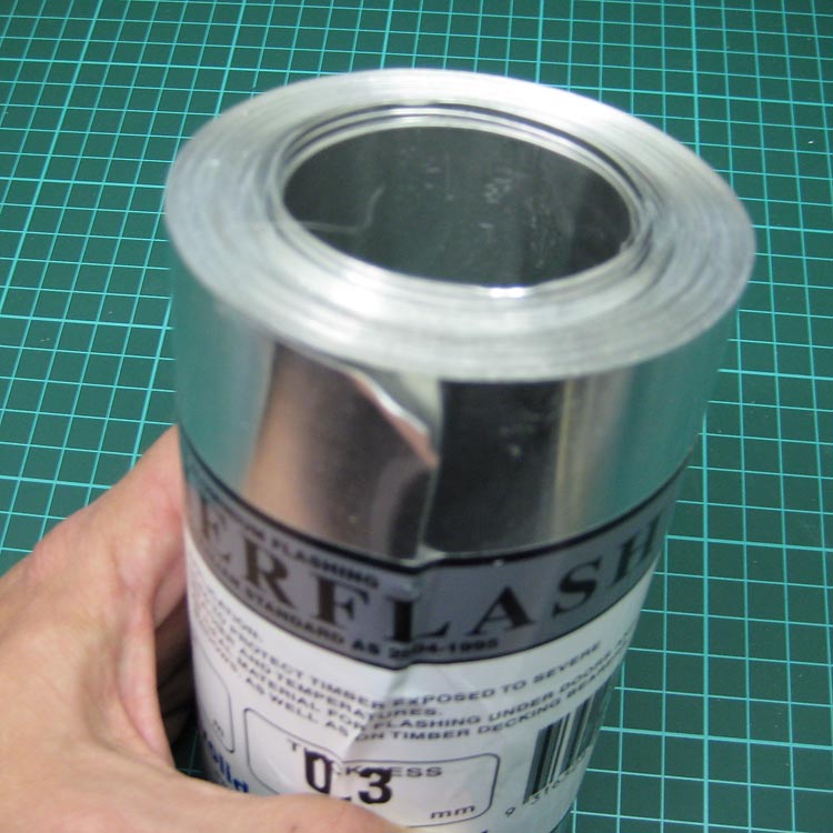
Aluminium sheet flashing. $16 for a 10 metre roll.
I gave the printed plans a very light spray with spray adhesive and stuck them to a piece of the aluminium flashing. I rolled the aluminium flat using an Exacto handle and a floor tile. Don't try this on your cutting mat or anything with even a little give, it will curl the metal.
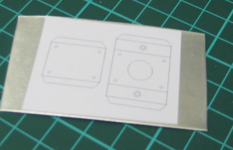
Wheel hoist plans glued to aluminium sheet.
Some of the holes were drilled prior to bending. This way, they could be drilled, filed, sanded and then flattened again. I also scored the fold lines with the back of a craft blade to ease the folding process.
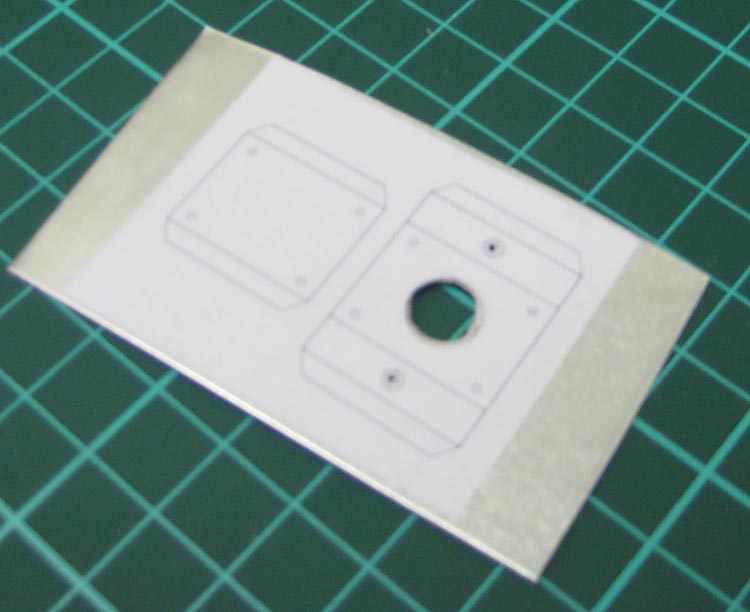
Holes drilled prior to folding.
This is where a good pair of scissors comes in handy. I have a nice strong pair of kitchen scissors that have a slightly serrated cutting edge. These work particularly well on the aluminium sheet as they tend to grab and hold the metal as you cut.
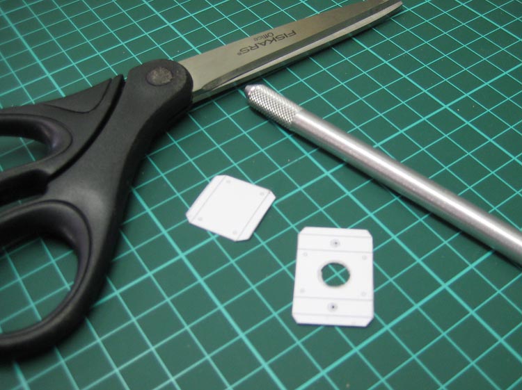
The alloy was cut with sturdy scissors.
I wanted some holes in the upper and lower sections to match so I could pass some rod through later. To achieve this I taped the two parts together and drilled them all at once.
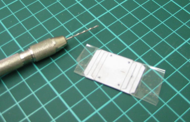
Taping the two parts together so the holes will match.
The paper plan was removed from the parts, the edges were filed and sanded smooth and then both sided were given a good scrub with a scourer to remove any glue residue and take off any remaining burrs.
Parts drilled, sanded and cleaned prior to folding.
The cover section was then folded up with a mini etch-mate device.
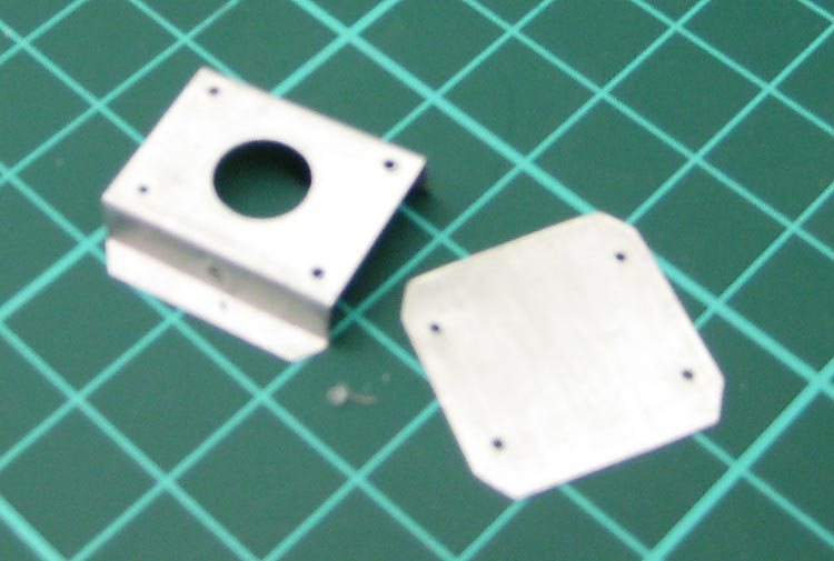
The folded pieces.
A dry run then took place to make sure the new hoist would fit where it was meant to.
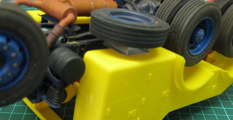
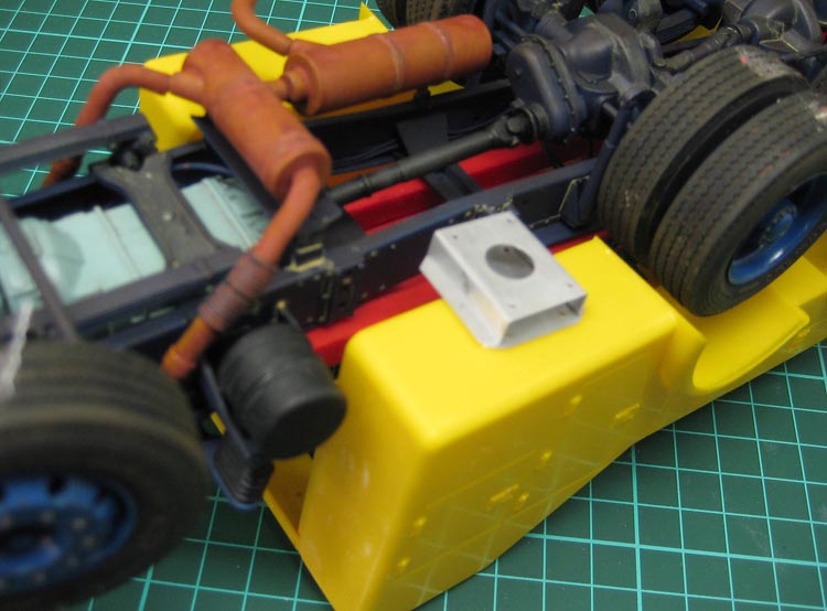
A dry run to check position of the spare and hoist.
Time for a final dry run and to glue on a couple more accessories.
Dry run. You can see a scratchbuilt broom and holder here.
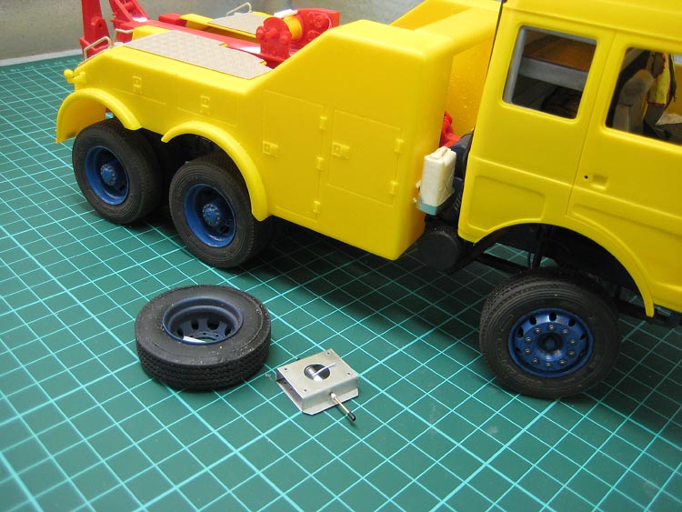
The finished wheel hoist and spare.
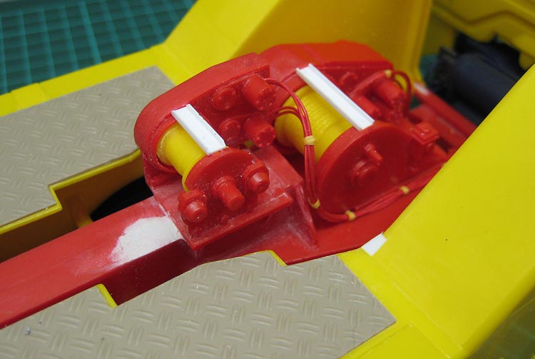
Hydraulic lines to the winch motors.
Overall view of the dry run.
Dry run complete, next stop: The paint shop! I guess I'd better finalise the colour scheme now...

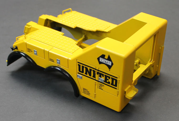
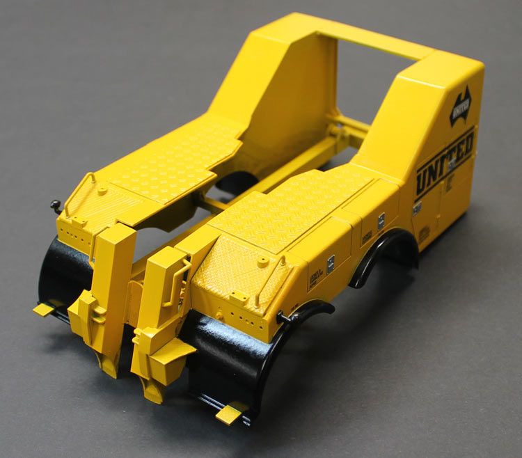
Guards sprayed black
Time for some paint. The body parts, being bright yellow plastic, were always going to need some solid priming. I first coated them with Citadel Skull White out of a rattle can. Seeing as their acrylics have such great covering power, I thought the primer would be a good choice. Not so. After many coats, the yellow was still showing through. Nothing for it but to hit it with some Mr Surfacer 500. Yellow-be-gone! Once this had hardened, I sprayed the wheel arches sating black.
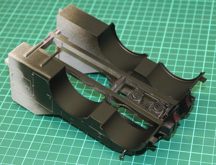
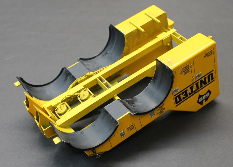
Under the arches
I used Citadel Skull Black through the airbrush for this.
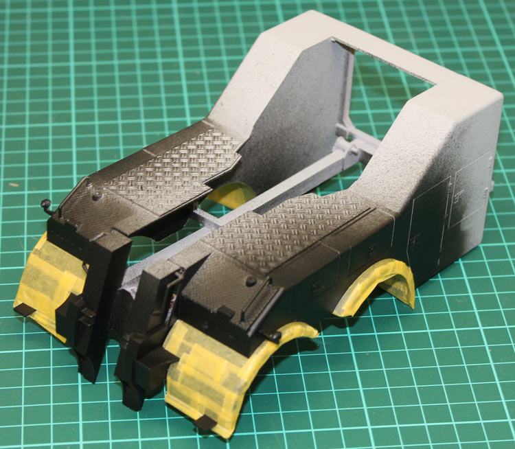
Masking the guards
I masked off the wheel arches in preparation for the top colour.
Finished bumper in place
I have just realised I have not taken any in-progress shots of the bumper being finished. The process was basically finishing off the construction, priming and painting. I added the aluminium cones to each of the headlight recesses, popped a small bead in the point of the cone as a bulb and glued the lenses in place. I used two of the kit lenses, with lines on, and two plain domes from the spares box, to look like spot lights.
Finished bumper in place
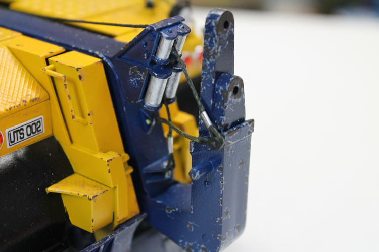
Decals, cable and scratchbuilt shackle were added and the whole lot grubbied up and chipped. This was my first attempt at chipping and I am quite pleased with the reults.
Lights, cable and shackle can be seen here.
The whole shebang was then glued to the front of the chassis with heavy liquid cement and left for several days to setup. The attachment points are relatively small so I am hoping the whole thing holds together.
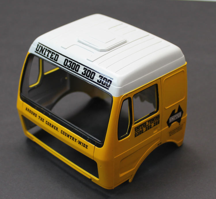
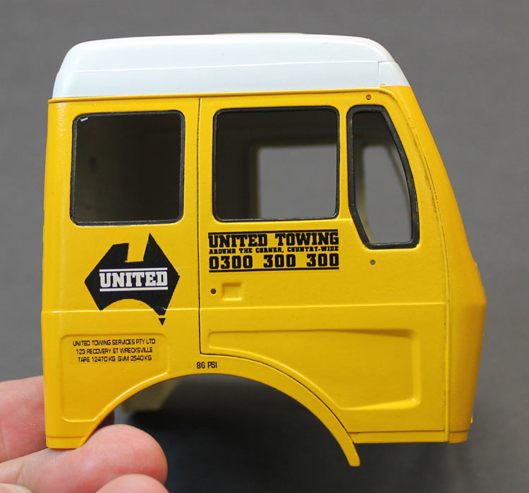
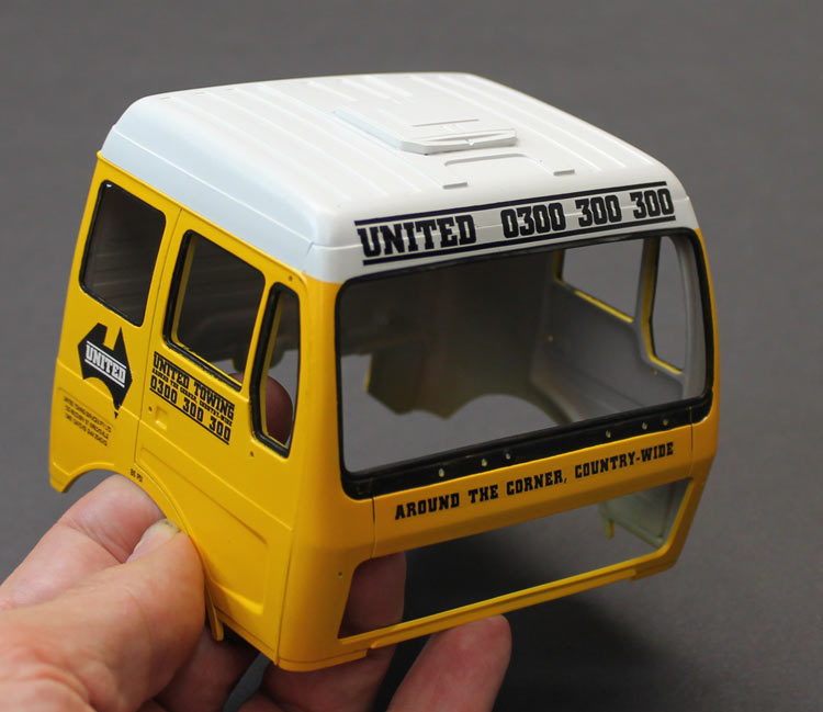
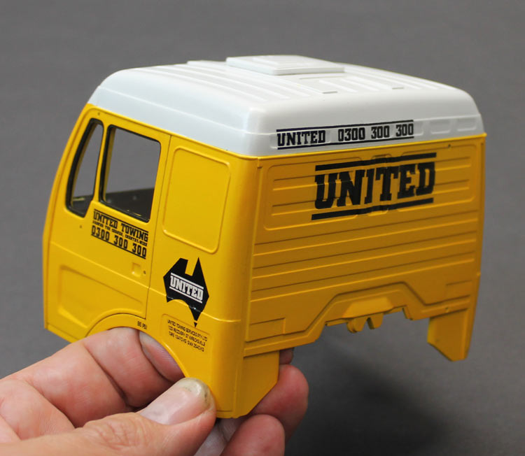
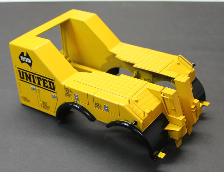
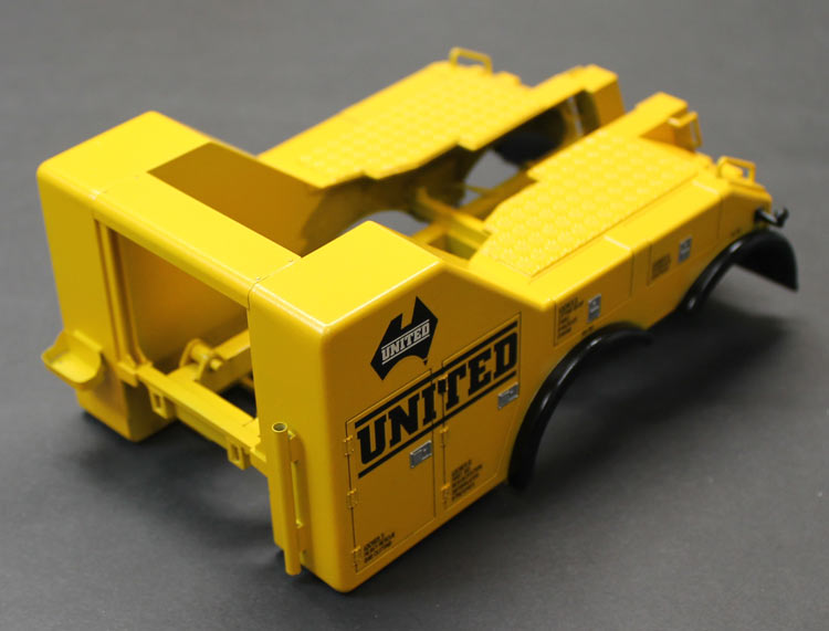
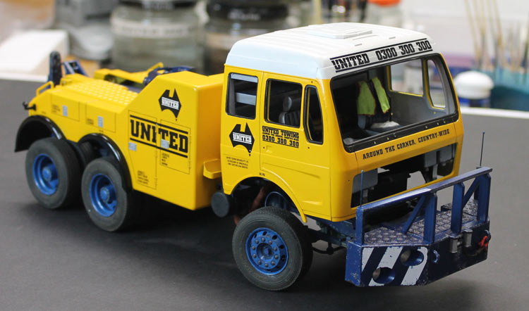
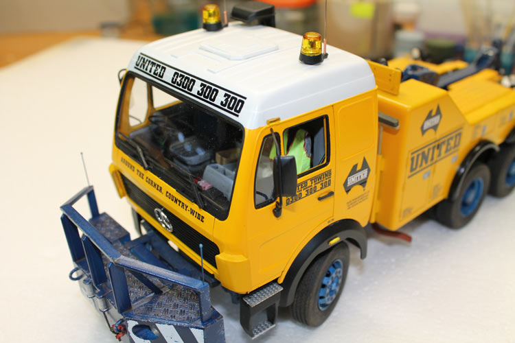
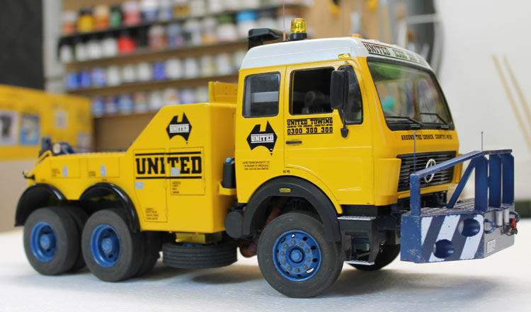
The cab painted and decalled
Painting the cab went by the usual procedure: prime, paint white, mask, paint yellow, gloss coat, decal, gloss coat. I wanted to try something different to the usual rattle-can paint job. I thought I'd try using matt paint through the airbrush and then glossing it up afterwards. I wanted to try this as yellow is a fairly hard colour to spray and often ends up translucent. I used Citadel yellow through the airbrush. It still took many, many coats, but I ended up with the solid colour I was after. I can't say I'm overly happy with the finish, though. It didn't really gloss up much at all.
I created the decals myself by doing artwork on the computer and running it through the laser printer onto clear decal sheet. I achieved the white behind the UNITED text in the map by placing a rectangle of white decal down before the black decal.
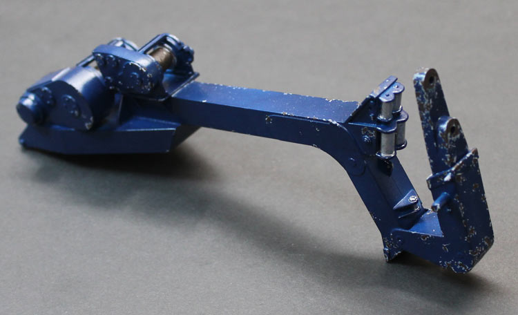
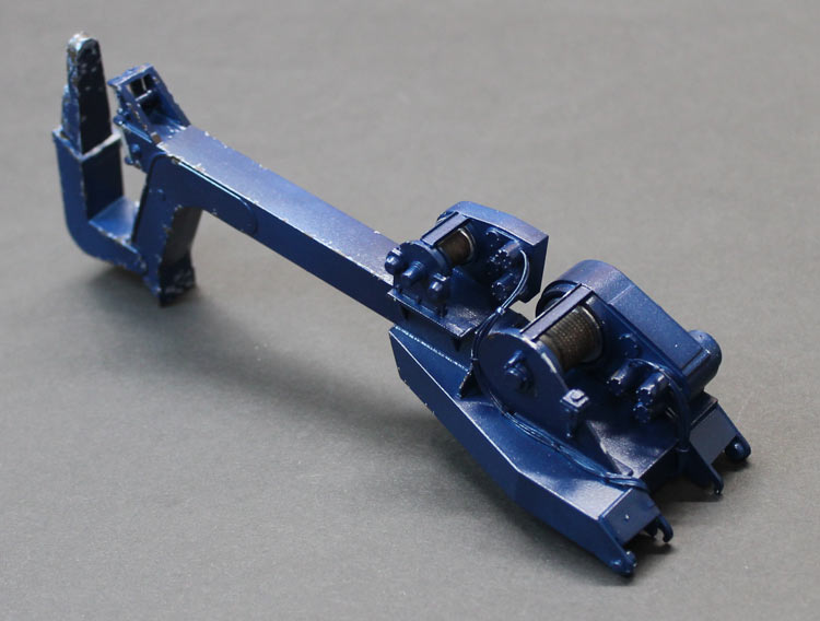
The tow boom painted and chipped up
The tow boom was prepped and primed and then top-coated with a Revell gloss dark blue paint chosen to contrast strongly with the body yellow. Some paint chipping was applied where most knocks would have happened.
The tow body sprayed up and decalled.
The tow body got the same treatment as the cab. The slam locks were masked and sprayed with Testors non-buffing Metaliser Steel. I've started applying a little weathering tothe underside. As the project gets closer to completion, I will match the underside gunge to the chassis so I don't get too much contrast.
Another dry run.
Time for another dry run. I am such a slow modeller that I end up trying all sorts of new techniques on the same model. Maybe that is why I am so slow! On this model I have introduced some metal, new weathering washes, chipping techniques, laser-print decals and a new painting technique. All in all I am really happy with the way this is coming together.
Umm ... I kind of finished and now realise I didn't take any more photos. I'll take some more now and go back over the processes.
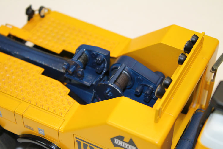
Winch cable.
I replaced the moulded kit winch cable with some braided fishing line from K-Mart. I've got enough now to do several hundred tow trucks. The ends were looped over and glued together with CA. Once that was set, I cut a strip of aluminium sheet from a Milo tin seal and glued one end to the join. Once that was set, I wrapped the balance of the strip around the join in the cable to secure it and make it look like a ferule.
I then fed that cable back through the beam and attached it to the winch drum with more CA. A wash of burnt umber gave it a nice metallic colur.
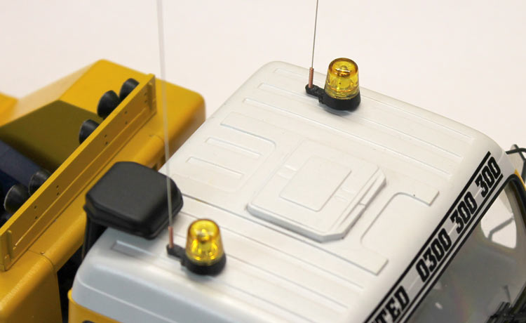
Antennae and lights.
The kit parts for the rotating beacons are supplied in clear plastic. I gave these a couple of coats of Tamiya clear yellow tint them appropriately. The antennae are accupuncture needles with both ends trimmed off. They come with nice brass windings around the handle end that look convincingly like springs. Be careful with these, they are designed to pierce the skin!
The indicators were, again, supplied as clear, so they got the same two coats of clear yellow. In order to give the indicators some level of reflectivity, I glued small rectangles of chrome mylar to the back of each. This gives them a nice glow effect.
Cab interior.
The cab interior went together with a bit of fettling. I had to trim off some of the edges of the interior bucket to get everything to settle in place nicely. I think there was some interference with the top of the cab interior and the strngthening I added earlier. Anyway, I got it all together in such a way that none of the joints are stressed. Ther's not much much I dislike more than having a seam pop at the end of a build.
Glazing went in without a hitch. I did have to add the steering wheel through the side window after everything else was in place as it fouled the dash when I slid the interior into place.
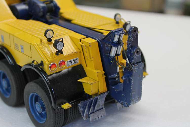
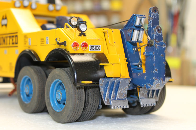
Tail-end
The rear indicator/brake light lenses were clear, too, so they were hit with transluent yellow and red and then glued to the chrome bases with PVA.
Summary
This was a thoroughly enjoyable, relaxing build. I think mainly because I just tackled one small job at a time and considered each a model in itself. That way I didn't have half-finished tasks hanging around that nagged at me until I would come back and rush just to get them out of the way. It was also very satisfying to try new techniques. As a result of this build I have now added about ten trucks and trailers to my stash and I'm also almost encouraged enough to restart my stalled Diamond Reo project!
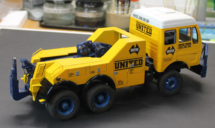
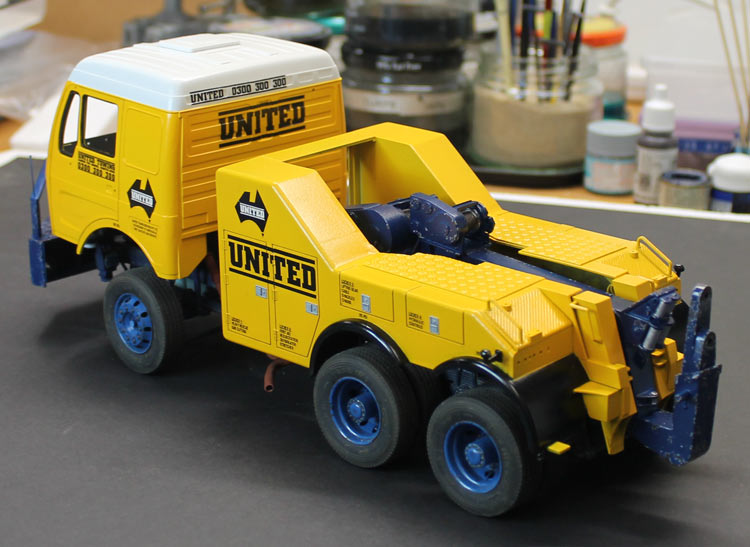
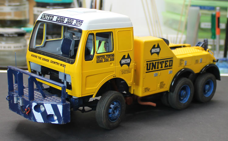
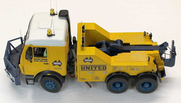
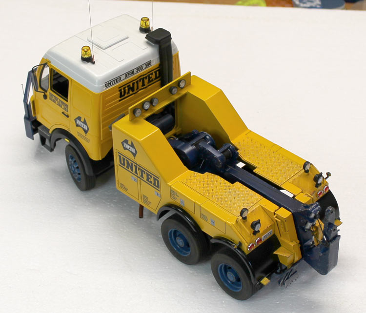
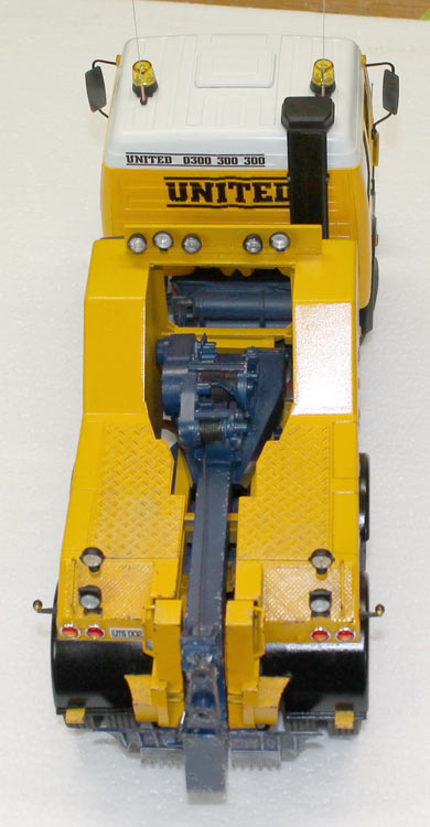
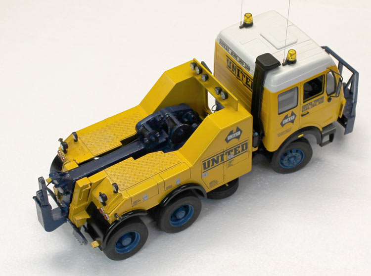
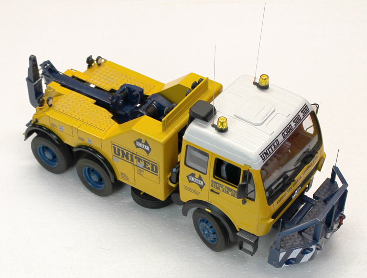
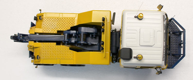
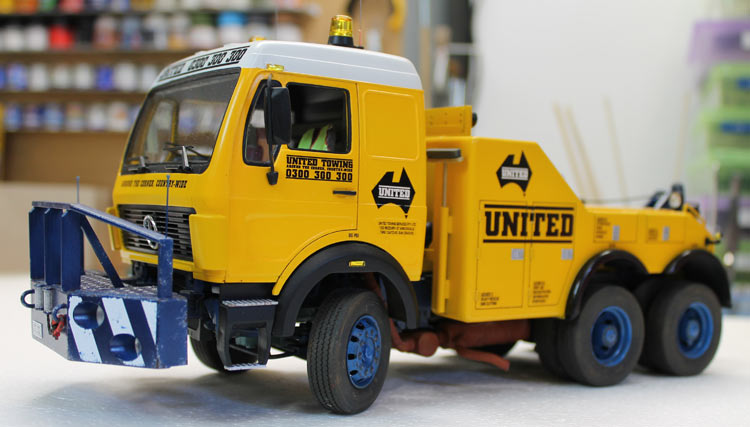
Here are a few pics of the final result:
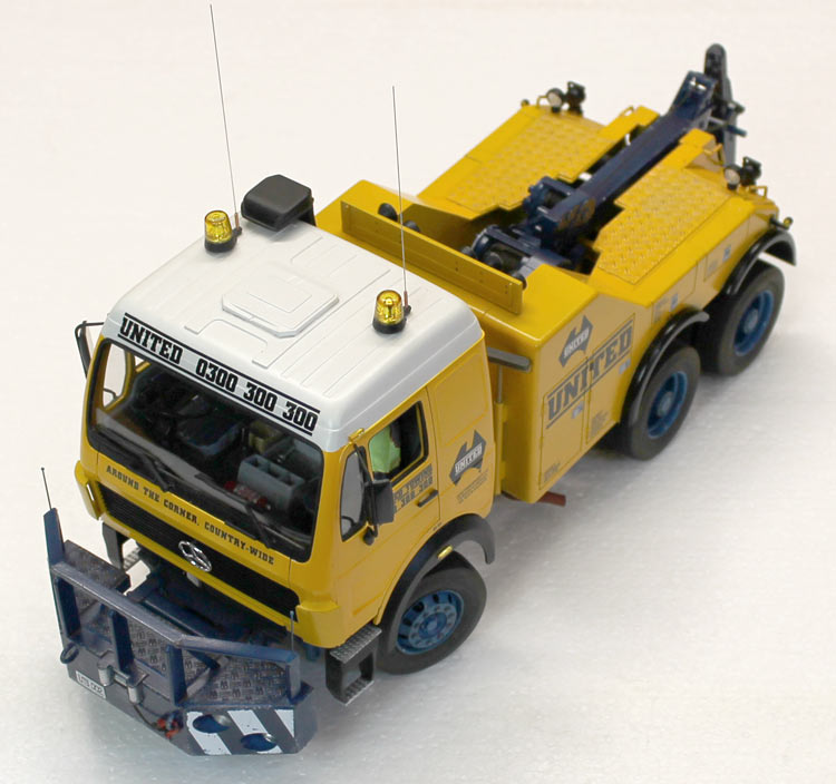
Go to Scale Modelling from Mercedes Wrecker
